Understanding the PIT test response and the meaning of an anomaly
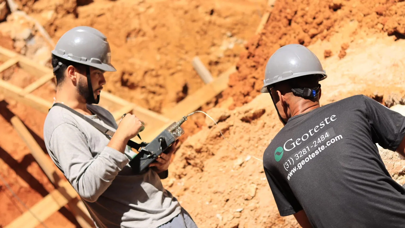
The Low Strain Integrity Test, widely known as PIT (Pile Integrity Test), is a non-destructive, low strain method. The requirement for pile integrity tests comes from ABNT NBR 6122:2019, with Amendment 1:2022, the standard for foundation design and construction. It is worth correcting a frequent misconception: ABNT NBR 16903:2020 deals with static load tests on deep foundations, and not with the integrity test. Its main objective is to verify the physical continuity and integrity of deep foundations through the propagation of low strain acoustic waves along the shaft.
The physical principle of the test is based on the one-dimensional wave theory. A blow with a low-mass hammer applied to the top of the pile generates a stress wave that travels down the shaft to the toe and returns to the sensor installed on the surface. Changes in the mechanical impedance of the pile cause intermediate reflections of this wave. Mechanical impedance is defined by the product of the cross-sectional area by the material's modulus of elasticity, divided by the wave propagation velocity in concrete.
When the reflectometry graph displays an abrupt variation before the toe reflection, it indicates an alteration in impedance. An anomaly detected in the PIT indicates that at a certain depth there was a variation in the cross-section, an alteration in the concrete quality, cracking, or an inclusion of soil or bentonite slurry. The interpretation of this event requires careful analysis to differentiate real defects from acceptable constructive variations.
Here is the most important point of this article: an anomaly indication in PIT does not equate to the confirmation of a structural defect. The test records impedance variations, and impedance variations have very different origins, some absolutely normal, such as a designed change in section, splice, metallic casing section, variation in surrounding soil stiffness, or quality of pile top preparation. The signal needs to be read in the context of the design, the construction log, the execution process, and the geotechnical profile, always by a qualified professional. When doubt persists, the correct technical conduct is complementary investigation, and not the immediate conclusion that the pile is compromised.
Classification of signals and types of anomalies in the shaft
PIT technical reports usually categorize evaluated piles into integrity classes, allowing prioritization of which elements require additional investigation.
Piles with confirmed integrity
They show a clear toe reflection, wave velocity compatible with the designed concrete strength, and absence of significant intermediate reflections. The shaft is considered continuous and without relevant impedance alterations.
Piles with moderate or inconclusive anomalies
They exhibit low-amplitude intermediate reflections that indicate small variations in the cross-section or small changes in material properties. In these cases, the toe signal can still be identified, but the element requires supplementary attention and construction log verification.
Piles with severe anomalies
They record high-intensity intermediate reflections, often with the same signal as the initial impact, indicating a drastic reduction in mechanical impedance, such as severe necking, shaft discontinuity, or very poor quality concrete. In these scenarios, the toe reflection is usually completely masked by the intermediate defect.
Physical limitations of PIT and causes of false positives
Before making drastic decisions, it is essential to understand the inherent limitations of the low strain method to avoid premature diagnoses.
- Soil damping: In very resistant soils or in piles with a high length-to-diameter ratio, the wave energy is dissipated by lateral friction, preventing the wave from reaching the toe or returning to the top with measurable amplitude.
- Multiple reflections: When there is an impedance variation near the top, the wave reflects repeatedly between this variation and the surface, creating secondary echoes in the graphs that can be confused with multiple defects along the shaft.
- Soil stratigraphy variations: Abrupt changes in the stiffness of soil layers crossed by the pile can generate reflections in the signal that resemble geometric variations of the shaft.
- Inadequate top preparation: Irregularities, degraded concrete, or the presence of exposed and loose rebar at the top of the pile distort the input wave, compromising the entire acquired signal.
Technical roadmap for pile investigation after anomaly
In the face of an anomaly detected in the PIT, the engineering team must follow a structured investigation flow to obtain a definitive diagnosis and guide corrective actions safely and economically.
Step 1: Retroactive analysis of construction logs and executive data
The first step consists of correlating the depth indicated by the PIT with the drilling and concreting record of the element. The local geotechnical profile should be verified through the SPT boring report, the actual concrete consumption compared to the theoretical volume, the occurrence of instabilities during excavation, the presence of groundwater, and eventual interruptions in concrete supply.
Step 2: Visual inspection and localized excavation
If the anomaly is indicated at shallow depths, generally up to two or three meters below the cut-off level, the most direct approach is to excavate the soil around the pile for visual and tactile inspection. This measure allows direct verification of the presence of necking, concrete voids, soil contamination of the concrete, or failures in the pile head preparation.
Step 3: High Strain Dynamic Test (PDA)
When the anomaly is located at greater depths, the PDA test, standardized by ABNT NBR 13208, is the most suitable tool. By applying higher energy impacts with an adequate reaction system, PDA provides quantitative information on the mobilized load capacity, the distribution of toe resistance and lateral friction, in addition to evaluating structural integrity through impedance analysis and the integrity factor. The test confirms whether the anomaly functionally compromises the pile under service loads.
Step 4: Internal shaft rotary drilling or Cross-Hole test
In large-diameter piles or in elements where previous access tubes were installed, the ultrasonic Cross-Hole test allows mapping the concrete quality between the tubes along the entire shaft. If no accessible tubes exist, rotary drilling of the pile core can be performed, extracting concrete cores for axial compression tests and visual inspection of the rock/concrete continuity at the toe contact.
Step 5: Static Load Test (SLT)
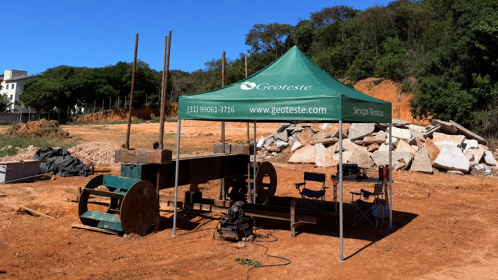
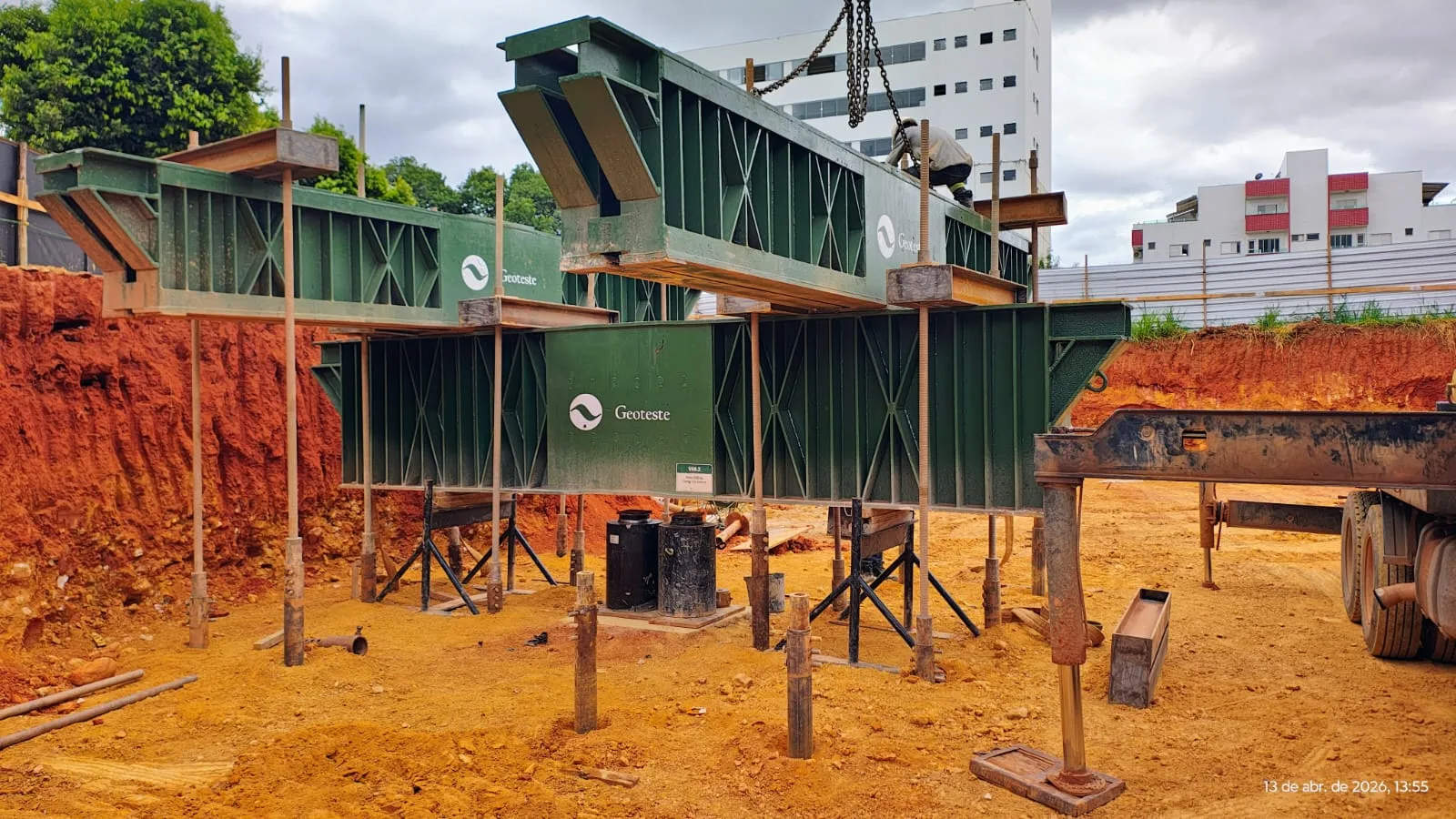
Considered the definitive method for performance homologation of deep foundations according to ABNT NBR 6122:2022, the Static Load Test subjects the pile to real load increments through hydraulic jacks and a reaction system. The SLT evaluates the load-settlement curve of the anomalous element, determining if the pile meets the stability and deformability criteria required by the structural design, even in the presence of local discontinuities.
Comparison of complementary investigation methods
| Investigation Method | Main Objective | Main Advantages | Main Limitations |
|---|---|---|---|
| Visual Inspection / Excavation | Direct verification of the shaft surface | Immediate conclusive diagnosis for the top | Restricted to shallow depths |
| PDA (NBR 13208) | Evaluate load capacity and integrity | Measures structural and geotechnical capacity | Requires impact and reaction system at the top |
| Core Rotary Drilling | Direct sampling of shaft concrete | Allows concrete compression tests | Punctual and locally destructive method |
| Ultrasonic Cross-Hole | Concrete mapping between tubes | High spatial resolution of defects | Requires prior installation of guide tubes |
| Static Load Test (NBR 6122) | Determine load-settlement behavior | Direct and definitive validation method | Higher cost and logistics than others |
Engineering decision and corrective actions
After completing the complementary diagnosis, the team composed of the foundation designer, structural engineer, and geotechnical consultant must deliberate on the fate of the founded element.
If high strain tests or the static load test demonstrate that the pile supports the design load with an adequate safety factor and without excessive settlement, the element can be released for use without interventions. If loss of structural or geotechnical capacity is proven, engineering solutions are defined, such as reinforcement by high-pressure cement grout injections, structural casing and capping of the shaft, or the execution of adjacent complementary piles with the resizing of the pile cap.
Specialist support from Geoteste in foundation diagnosis
Geoteste has vast experience in identifying and advanced investigation when an anomaly detected in PIT is recorded on construction sites. Our team operates in strict compliance with ABNT NBR 16903, NBR 13208, and NBR 6122:2022 standards, providing conclusive technical reports that avoid unnecessary disposal of foundation elements or risks to structural stability.
We offer complete support from the execution of supplementary PIT tests with high-resolution equipment, through the performance of high strain PDA tests, to the assembly and application of complete Static Load Tests. Count on our specialist engineers to prepare an accurate diagnosis for your project and recommend the most technically viable solution for your construction. Contact Geoteste's technical team and request an evaluation for your project.