The monitored continuous flight auger pile has consolidated its position as one of the most widely used deep foundation solutions in Brazil due to its high productivity, reduced noise disturbance, and absence of vibrations detrimental to neighboring constructions. However, the geotechnical design of this solution still imposes complex challenges on designers and consultants. Traditional semi-empirical formulations often show wide dispersion in estimating the total bearing capacity, as well as in the actual distribution of forces between lateral skin friction along the shaft and toe resistance at the base of the element.
When a conventional static load test is performed exclusively with surface readings, the global load versus settlement curve is measured at the pile top. This traditional test, regulated by ABNT NBR 16903:2020, allows the evaluation of the element's performance under test loads, but keeps the shaft as a black box. It becomes unfeasible to accurately determine what portion of the applied load was dissipated by skin friction in each stratigraphic layer and what portion reached the pile toe. To address this design gap and allow for rational and optimized foundation engineering, the instrumented continuous flight auger pile emerges as the primary experimental tool for deep investigation.
The concept and objectives of in-depth instrumentation
The instrumented continuous flight auger pile consists of installing sensors along the depth of the reinforcement cage to measure mechanical quantities, specific strains, or relative displacements during the application of axial loading in the static load test. The fundamental objective of this procedure is to obtain the load transfer curve at multiple levels of the pile, enabling the calculation of the following geotechnical variables:
- Remaining axial load in each instrumented section along the shaft.
- Average mobilized lateral skin friction in each soil stratum crossed by the element.
- Portion of load effectively transferred to the pile toe at the contact with the bearing soil.
- Mobilization curves of unit lateral skin friction as a function of local displacement (t-z curves).
- Mobilization curve of toe resistance as a function of base settlement (q-w curve).
- Tangent or secant modulus of elasticity of the concrete shaft throughout the loading stages.
This data provides subsidies for calibrating coefficients of predictive design methods, verifying parameters adopted in the guidelines of ABNT NBR 6122:2019 with Amendment 1:2022, and supporting eventual project revisions with substantial gains in technical safety and structural economy.
Types of sensors and internal measurement systems
The instrumentation of cast-in-place elements requires sensors with stiffness, measurement range, and mechanical protection compatible with the concreting environment and geotechnical loading. In foundation engineering practice, two major groups of devices are used for internal measurement.
Strain gauges
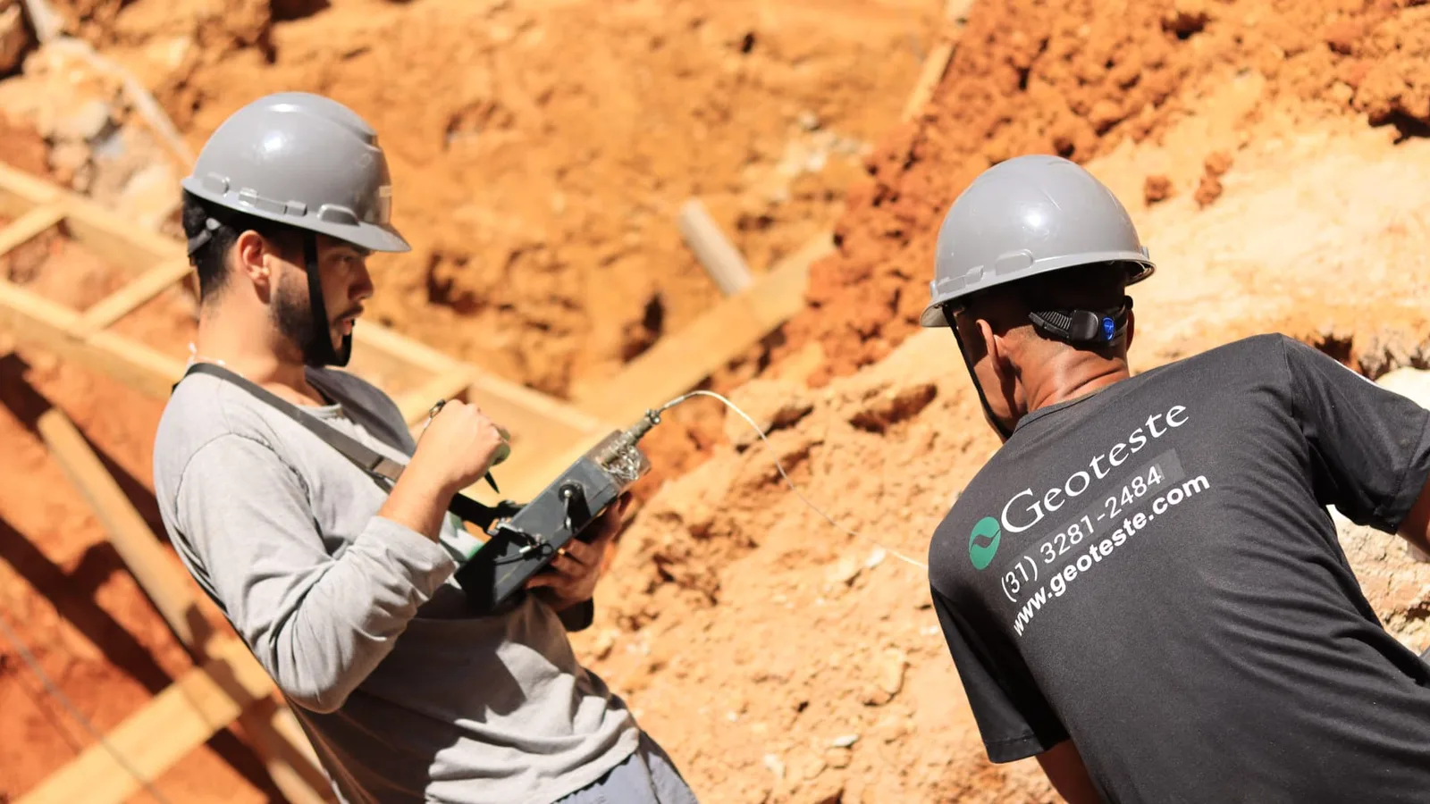
Specific strain gauges, usually called strain gauges, can be electrical resistance or vibrating wire type. In the case of excavated piles and continuous flight auger piles, the safest and most frequent format is the instrumented bar (sister bar). The sister bar consists of a small section of ribbed steel bar, identical to the pile reinforcement, which houses the hermetically sealed sensor in its core.
This instrumented bar is welded or tied to the reinforcement cage at the desired elevation, integrating into the concrete matrix during hardening. The vibrating wire shows remarkable long-term signal stability and low sensitivity to humidity variations compared to purely resistive systems, making it the standard in rigorous experimental campaigns.
Rod extensometers at depth (telltales)
Telltales, also known as mechanical rod extensometers, consist of guide tubes installed along the reinforcement, inside which metal rods run, detached from the side walls. The lower end of the rod is rigidly anchored at the elevation to be monitored, while the upper end reaches the surface at the pile top.
When the pile is compressed and deforms under the hydraulic jack's load, the rod transmits the absolute displacement of that deep point to the pile head, where a dial gauge or linear displacement sensor measures the relative variation between the anchorage point and the top. With two or more rods anchored at different elevations, the average shortening of the section between the anchorages is obtained.
Determination of axial stiffness and deformation modulus of the shaft
The physical principle governing the conversion of measured strains into axial forces is based on solid mechanics. According to Hooke's Law, the axial force acting on a given cross-section is the product of the specific strain by the axial stiffness of the composite section made of concrete and steel.
The elementary expression states that the load is equal to the product of the specific strain by the cross-sectional area and the material's modulus of elasticity. However, concrete exhibits non-linear mechanical behavior. The secant modulus of deformation of concrete progressively reduces as compressive stress levels increase. Furthermore, the actual cross-section constructed in a continuous flight auger pile often presents overconsumption of concrete in soft soil layers, generating local variations in diameter.
To circumvent this rheological uncertainty, the established technical methodology adopts a calibration section at the pile top. In the upper section, which is embedded near the surface or in excavated soil without significant lateral friction, the axial load applied by the hydraulic jack is fully known through the load cell positioned at the top. The direct relationship between the force applied to the pile cap and the strain recorded by the sensors of the first instrumented level allows calibrating the actual secant deformation modulus of that element for each loading increment.
Interpretation of load distribution and lateral friction
With the secant modulus profile properly calibrated at each load stage, the remaining axial forces are calculated at each instrumented elevation of the pile. The difference in axial load between two consecutive sensor levels represents the portion of load transferred to the soil mass in that respective segment.
Dividing this transferred load by the nominal lateral area of the shaft in that section yields the average mobilized unit lateral skin friction for the interval. The load that reaches the last instrumentation level, positioned just above the pile base, represents the mobilized toe resistance for that loading stage.
The table below summarizes the main operational and analytical differences between the two most common instrumentation methods for deep piles.
| Analysis criterion | Strain gauges (sister bars) | Rod extensometers (telltales) |
|---|---|---|
| Quantity measured in the field | Local specific strain (microstrain) | Displacement and elastic shortening of section (mm) |
| Analytical precision | Allows detailed and continuous discretization | Measures the integrated average behavior of the section |
| Installation complexity | Prior fixing with tying of electrical cables | Fixing of guide tubes and mechanical anchorages |
| Data acquisition | Automated by datalogger systems | Manual or automated by transducers at the top |
| Sensitivity to execution damage | Requires protection against impacts and water | Requires assurance against crushing of guide tubes |
| Friction interpretation | Point-based per instrumented level | Average between anchorage intervals |
Kinematics of toe resistance and lateral skin friction mobilization
One of the most relevant insights generated by the instrumented continuous flight auger pile load test concerns the distinct kinematics of mobilization between the shaft surface and the pile base. This behavior is widely reported in scientific publications of prominent geotechnical events, such as the Brazilian Congress of Soil Mechanics and Geotechnical Engineering (COBRAMSEG) and the Seminar on Special Foundation Engineering and Geotechnics (SEFE), in addition to theses developed at research institutions like Unicamp.
The unit lateral skin friction reaches its maximum mobilization with extremely small relative displacements between soil and pile, typically between 2 mm and 5 mm, regardless of the element's diameter. Once this interface shear level is reached, the lateral skin friction resistance tends to stabilize or suffer a slight loss due to cyclic softening in more sensitive soils.
On the other hand, toe resistance requires substantially larger axial displacements to be significantly activated. In excavated piles and continuous flight auger piles, experimental geotechnical literature demonstrates that almost total mobilization of the toe bearing capacity requires settlements at the base of the order of 10% to 20% of the pile diameter. Since admissible or service loads in foundation projects are limited by strict criteria of tolerable settlement in the structure, the toe portion in continuous flight auger piles of representative length contributes a minority fraction of the total load at normal operating levels.
In long elements, almost all of the service loading is supported by lateral skin friction along the shaft. Toe resistance fundamentally acts as a reserve of geotechnical capacity, mobilized only when lateral skin friction is fully exhausted or when the element undergoes displacements far exceeding the average values of structural operation.
Specific executive challenges of the continuous flight auger pile
Performing tests with instrumented continuous flight auger piles imposes executive challenges that differentiate them from driven piles or excavated piles with stabilizing fluid. In the continuous flight auger execution process, the helical auger drills the ground to the design elevation, and concrete with high slump is injected under positive pressure through the central stem as the auger is extracted.
The reinforcement cage is obligatorily introduced after the concrete placement of the pile, descending into the fresh concrete by its own weight or with moderate aid of top vibrators. This procedure requires extreme technical care during the preparatory phase:
- Firm attachment of the sensors to the internal longitudinal bars of the cage to prevent rotation or displacement during descent.
- Mechanical protection of electrical cables or hoses against shearing and friction with dense concrete and aggregates.
- Prevention of twisting in the reinforcement that could damage instrument connections.
- Ensuring the verticality of the cage during descent, preventing the tip of the reinforcement from colliding with the excavated soil walls.
- Adoption of resistant plastic spacers along the entire length of the cage to ensure concrete cover and preserve the sensors.
Any anomaly in the reinforcement cage descent process can cut electrical conductors or recalibrate the instruments, compromising continuous data acquisition during the static load test.
The role of instrumented load tests in project optimization
The static load test performed according to the requirements of ABNT NBR 16903:2020 gains a qualitative leap in relevance when combined with depth instrumentation. The methodology allows the geotechnical engineer to compare theoretically calculated unit resistances with the actual values developed in each soil layer during the test.
If the analysis demonstrates that lateral skin friction in a given layer of stiff or dense soil presented unit values superior to commonly conservative empirical correlations, pile lengths in projects with a large volume of repetition can be readjusted. Similarly, when it is found that the toe soil offers low contribution due to stress relief or the presence of excavation debris, the project can be corrected with full technical support and structural safety, aligning strictly with the performance criteria provided in ABNT NBR 6122:2019 with Amendment 1:2022.
Geoteste's solutions in instrumented load tests
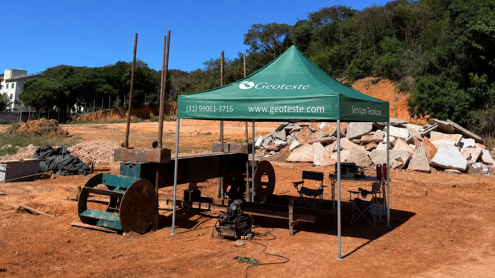
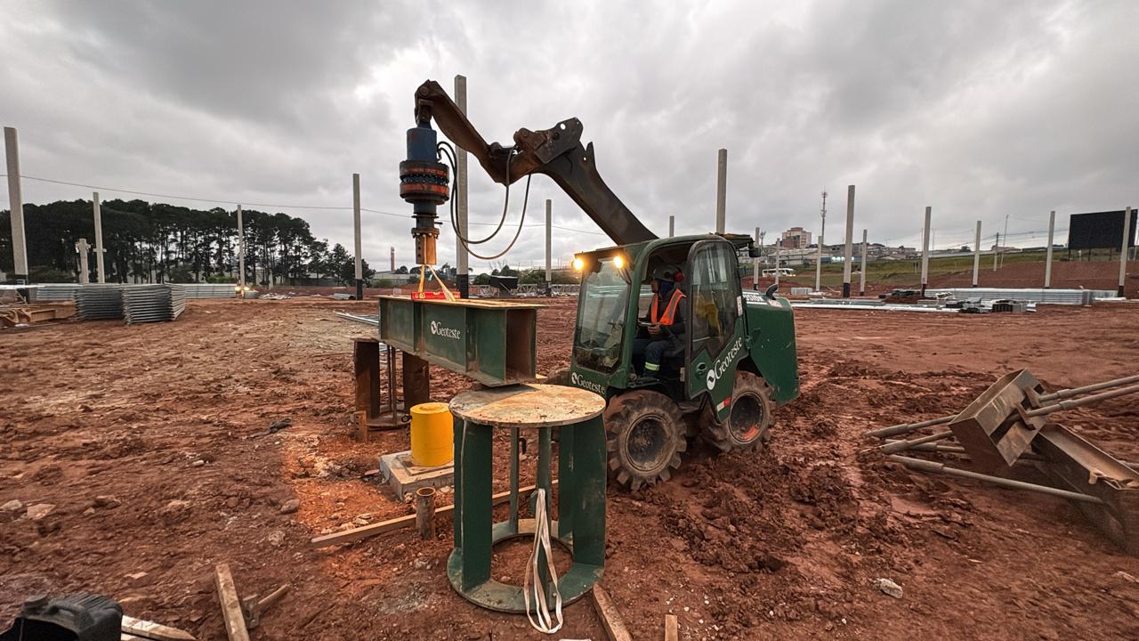
Geoteste operates with extensive experience and methodological rigor in the execution of axial static compression and tension load tests on continuous flight auger piles, in strict compliance with ABNT NBR 16903:2020. The company provides all the necessary apparatus for controlling depth instrumentation, integrating calibrated load cells, automatic displacement reading systems, assembly of anchored reaction beams, and specific strain sensors or extensometers designed for severe construction site conditions.
By combining static tests with other geotechnical quality controls and ensuring compliance with the design guidelines of ABNT NBR 6122:2019 with Amendment 1:2022, the Geoteste technical team transforms raw field data into consolidated reports of load transfer and precise geotechnical parameters. Contact our expert engineers to plan the instrumentation and load test for your next project with complete technical reliability.