Helical reaction system for SLT: operation, design, capacity, and advantages of the SAP
How the helical reaction system works in static load tests: uplift principle, design, comparison with kentledge and reaction piles, and application limits.

Por Dr. Celso Gontijo
Engenheiro Civil Geotécnico
CREA/CONFEA 1404864105
The problem the reaction system solves
Every static load test requires something to push against. The hydraulic jack applies load to the pile head, and this load needs an equivalent reaction, in the opposite direction. Historically, this reaction is obtained in two ways: a kentledge, which is a mass supported on a platform, or tensioned reaction piles, connected to a beam over the tested element.
Both solutions work, and both are expensive. Kentledge requires the transport and handling of a large volume of mass on site. Reaction piles require the execution of additional elements, reinforcement, concrete pouring and, mainly, curing time before the test can begin. On many construction sites, the timeline for the reaction system is longer than the timeline for the test itself.
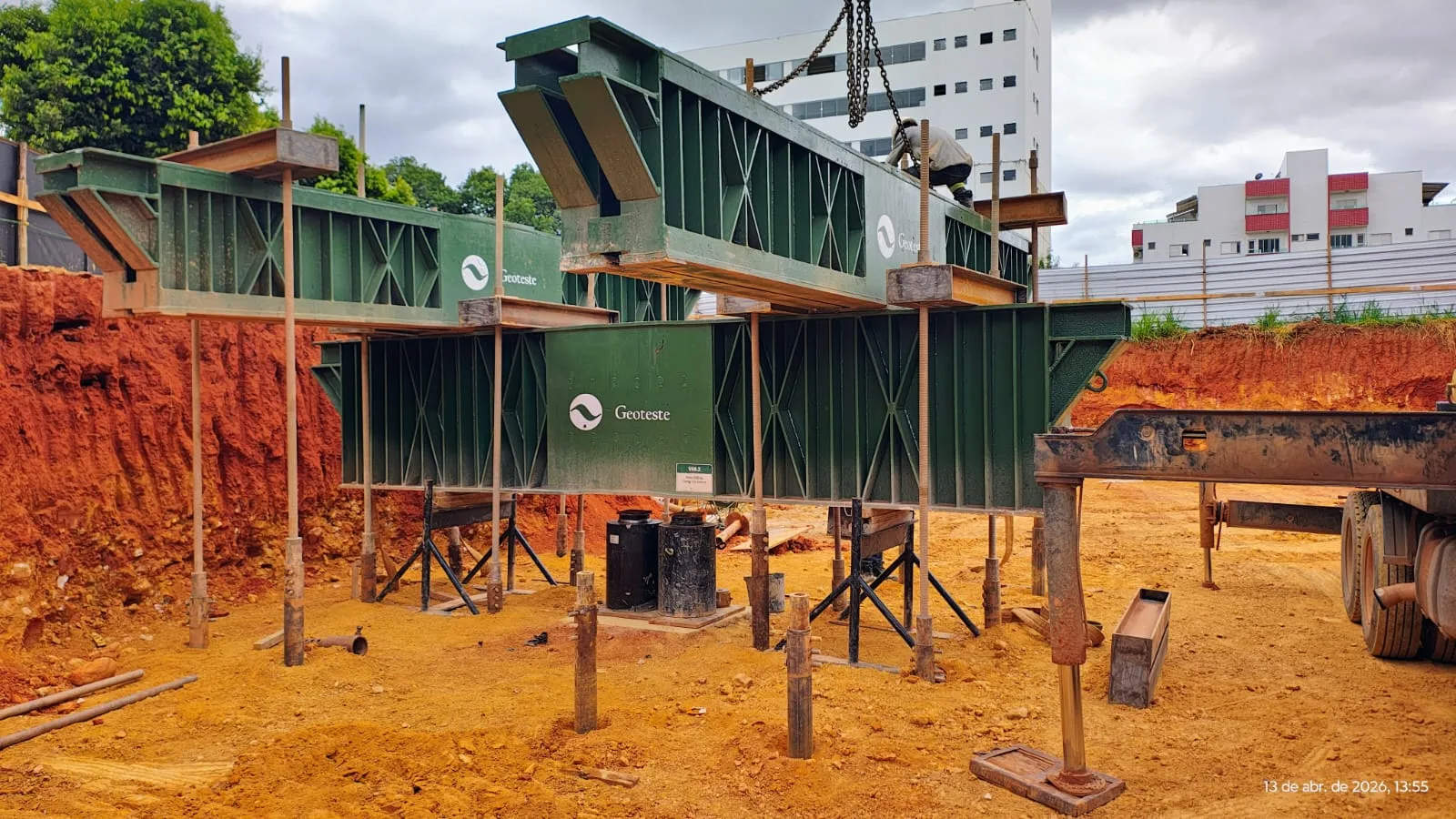
The helical reaction system directly addresses this bottleneck. Instead of constructing concrete reaction elements, it uses helical anchors installed by rotation into the ground, which work in tension and support the metallic reaction structure. This is the principle behind Geoteste's Temporary Anchoring System (SAP).
How helical reaction works
The helical anchor is an element composed of a central shaft and one or more helices welded along its length. It is installed by rotation, with torque application, without prior excavation and without concrete. As it rotates, the helices advance into the ground and begin to mobilize uplift resistance by the bearing of the soil on the surface of each helix, added to the lateral friction along the shaft.
Once the assembly is complete, the test logic is the same as for conventional static load tests: the hydraulic jack pushes the pile head downwards, the reaction beam receives the opposing force and transmits it to the anchors, which resist in tension. Loading is applied in stages, with settlement measurement at each stage, according to ABNT NBR 16903:2020.
Execution stages
- Design. Definition of the number of anchors, the diameter and number of helices, the installation length, and the geometric arrangement, based on the maximum test load and the geotechnical profile.
- Torque installation. Driving by rotation at the defined positions, with monitoring of the applied torque, which serves as a field indicator of the mobilized capacity.
- Assembly of the reaction structure. Positioning of the metallic beams and connection to the anchors.
- Test execution. Loading in stages, reading of settlements, and construction of the load-settlement curve.
- Demobilization. Removal of the beams and uninstallation of the anchors by reverse rotation, with reuse of the assembly in another test.
Design: what governs capacity
The uplift capacity of a helical anchor depends on a set of factors that must be evaluated on a case-by-case basis by the responsible engineer:
- Geotechnical profile. Strength of the layers penetrated and, especially, of the layer where the helices are embedded. Soft soils, uncontrolled fills, and high groundwater levels reduce the available capacity.
- Helix geometry. Diameter, quantity, and spacing between helices define the mobilized area and the failure mode, which can be by a soil cylinder between helices or by individual bearing of each helix.
- Installation depth. The relationship between depth and helix diameter distinguishes shallow from deep behavior, with a direct reflection on uplift resistance.
- Installation torque. There is a well-established correlation in practice between the final installation torque and the uplift capacity, used as a field verification. This is an empirical correlation that confirms the design but does not replace it.
- System arrangement. Number of anchors, distance between them, and distance to the tested pile, in order to avoid interference between stress bulbs and influence on the tested element.
- Structural verification. Strength of the shaft, helices, connections, and metallic beams for the maximum predicted load, with adequate safety factor.
The design parameters are defined for each project based on the maximum test load, the geotechnical profile, and the access and assembly conditions. The configuration actually employed and the capacity verifications must be included in the project and the test report.
Comparison between reaction systems
| Criterion | Concrete reaction piles | Kentledge | Helical reaction |
|---|---|---|---|
| Time until test start | Depends on concrete execution and curing | Depends on transport and assembly of mass | Installation by rotation on the same day |
| Permanent elements in the ground | Yes, additional piles | No | No, the assembly is removed |
| Reuse | No | Partial | Yes, the assembly is reusable |
| Logistical volume on site | Medium | High | Low |
| Waste generation | Concrete and reinforcement | Low | Practically none |
| Main restriction | Cost and schedule | Space and access on site | Available capacity in the geotechnical profile |
Application limits
The helical system is not universal, and presenting it as a solution for any scenario would be technically dishonest. The reaction depends on the ground resisting tension, and there are situations where this does not occur with the necessary margin: very soft superficial layers, heterogeneous fills, profiles with obstructions and boulders that prevent installation by rotation, and very high test loads in low-strength soils. In these cases, the appropriate solution may be conventional reaction piles or the bidirectional test, which dispenses with external reaction by loading the pile against itself.
The correct decision stems from the site investigation, the intended test load, and the site restrictions, and is made during the planning phase of the testing program, not on the day of mobilization.
Where the gain appears in the project
The economic benefit of the helical reaction is not only in the cost of the system. It is in the schedule. In projects where piling is on the critical path, anticipating the load test means anticipating the design decision it supports. This anticipation is what allows converting the test result into real optimization of the piling, a topic covered in load tests and cost reduction.
Technical support from Geoteste
Geoteste developed and operates the Temporary Anchoring System (SAP), its own helical reaction solution for static load tests, performed according to ABNT NBR 16903:2020 and within the requirements of ABNT NBR 6122:2019, with Amendment 1:2022. Learn about the Temporary Anchoring System, see the static load test service, or estimate your project plan in the test dimensioner.
Technical references
- ABNT NBR 6122:2019, with Amendment 1:2022. Design and execution of foundations. Rio de Janeiro: ABNT.
- ABNT NBR 16903:2020. Soil: static load test on deep foundation. Rio de Janeiro: ABNT.
- ABNT NBR 5629:2018. Execution of ground anchors. Rio de Janeiro: ABNT.