Instrumented Pile: How In-Depth Instrumentation Reveals Load Transfer Along the Shaft
Understand how instrumented piles allow for load transfer measurement, separating skin friction and end bearing resistance. Read our technical article.

Por Dr. Celso Gontijo
Engenheiro Civil Geotécnico
CREA/CONFEA 1404864105
How instrumentation transforms the understanding of deep foundation real behavior
I have been working in geotechnical engineering since 1956 and, over seven decades of professional activity, I have had the privilege of witnessing an extraordinary transformation in how we investigate the subsurface, design foundations, and evaluate their behavior. I have seen engineering evolve from a practice heavily reliant on field experience, relatively simple calculation methods, and essentially mechanical instruments to an increasingly data-driven discipline supported by high-precision sensors, automated data acquisition, real-time monitoring, and advanced interpretation methods. This technological evolution, however, has not diminished the importance of accumulated experience; on the contrary, it has made the ability to critically interpret what instruments reveal even more valuable. Among the most relevant advances, I consider the instrumentation of deep foundations to be particularly significant, as it allows engineers to observe phenomena that for decades remained hidden beneath the ground: how load is distributed along the shaft, how much each soil layer effectively contributes to pile resistance, and what portion of the forces reaches the toe. This article discusses these fundamentals, their technologies, and, above all, the contribution this information can offer for safer, more accurate, and more efficient foundation engineering.
Fundamentals of Instrumentation in Deep Foundations
The design of deep foundations traditionally relies on theoretical models, semi-empirical correlations, and preliminary field tests to estimate geotechnical bearing capacity. During a conventional static load test, performed according to the guidelines of ABNT NBR 16903:2020 and in the context of a project governed by ABNT NBR 6122:2022, the engineer obtains the global response of the element through the load versus displacement curve at the top. However, this external measurement does not directly inform how the applied stresses are absorbed along the different soil horizons encountered.
Performing the test on an instrumented pile fills this gap by recording deformations and displacements at pre-defined depths. With pile instrumentation, it is possible to quantify the fraction of the load absorbed by skin friction in each stratigraphic layer and accurately identify the magnitude of end bearing resistance mobilized for each loading stage.
Shaft deformation mechanisms and elastic shortening
The mechanical response of a deep foundation element under axial compression loading involves two fundamental displacement components: shaft deformation, associated with the elastic shortening of the pile’s constitutive material, and rigid body displacement resulting from the mobilization of the soil at the interface and at the toe.
When axial load is applied at the top section, the stresses induce a specific deformation that varies with depth. As the pile moves vertically relative to the surrounding ground, skin friction resistance is progressively mobilized from top to bottom. Due to this continuous transfer of forces to the soil mass, the normal force acting in the shaft decreases with increasing depth, reaching only the portion to be transmitted as end bearing resistance at the base section.
The total elastic shortening of the element corresponds to the integration of specific deformations along the effective length of the pile. Distributed instrumentation allows the shaft to be discretized into known segments, enabling the calculation of the elastic shortening of each segment individually.
Types of sensors and instrumentation techniques
To measure the physical quantities necessary for load transfer analysis, geotechnical engineering employs different instruments, installed before or during pile concreting, attached to the rebar cage, or inserted into specific access tubes.
Rod extensometers or tell-tales
Rod extensometers, often called tell-tales, are mechanical devices composed of rigid metal rods that extend from the surface to specific anchorage points at deep elevations of the pile. The rods are installed inside protective tubes that eliminate contact with the concrete, ensuring freedom of relative movement.
By monitoring the displacement of the rod top relative to the pile top using dial gauges or displacement transducers, the average elastic shortening of the section between the top and the anchorage point of that rod is obtained. Comparing readings from rods anchored at different depths allows calculation of shortening in each interval and inference of absolute toe displacement.
Electric and vibrating wire strain gauges
Strain gauges measure the local specific deformation of the pile section. They can be glued directly onto the steel reinforcement bars, encapsulated in welded supports, or embedded inside concrete blocks made with the same material as the pile, called sister bar type gauges.
Vibrating wire sensors are notable for their high long-term stability and resistance to moisture variations and electromagnetic noise on the construction site. From the record of micro-deformation at each load stage, the constitutive relationship of the material is applied to calculate the corresponding normal force in the instrumented section.
Calculation methodologies and load transfer
The interpretation of data obtained from an instrumented pile is based on the principles of static equilibrium and deformation compatibility. Among the classic references established in technical literature for interpreting instrumented tests, the methodology proposed by Bengt Fellenius stands out.
For each instrumented section under a given applied load at the top, the internal normal force is calculated by the product of the measured deformation, the secant or tangent modulus of deformability of the composite material, and the cross-sectional area. The difference in normal force between two consecutive instrumentation levels represents the load transferred to the soil by skin friction in that segment:
The normal force at the top of each segment subtracted from the normal force at the base of the segment provides the total force absorbed by skin friction in the section.
The average unit skin friction stress is obtained by dividing the transferred force by the corresponding segment's lateral surface area.
The normal force calculated at the level of the last sensor, located just above the base, defines the portion transferred as end bearing resistance.
The correlation of these values with settlement curves allows plotting load transfer curves, also known as t-z curves for skin friction along the shaft and q-w curves for resistance mobilized at the toe.
Determination of the modulus of deformability
One of the critical aspects in analyzing load transfer in cast-in-place concrete elements, such as continuous flight auger (CFA) piles and bored piles, is the realistic evaluation of the shaft’s modulus of deformability. The assumption of a constant and purely elastic modulus throughout the entire loading can introduce systematic errors in the determination of normal forces.
As demonstrated in national geotechnical research, such as studies presented at VI COBRAMSEG/COBRAMSEJ focused on the behavior of instrumented continuous flight auger piles, the concrete's modulus of deformability exhibits non-linear behavior, decreasing as deformations increase. The use of methods like that proposed by Fellenius, which adjusts the axial stiffness of the shaft as a function of the micro-deformation measured in the initial levels of the pile where skin friction has not yet reached high values in the initial phases, ensures greater rigor in separating the resistant portions.
Additionally, variations in the actual pile diameter along the stratigraphic profile due to concrete overconsumption must be considered in calculating the cross-sectional area, avoiding distortions in the conversion of micro-deformations into axial stresses.
Comparison of instrumentation methods
The choice of instrumentation system depends on the pile type, the geotechnical characteristics of the ground, the required precision, and the construction site conditions. The following table summarizes the main features of each technique.
Instrumentation Method | Measured Quantity | Technical Advantages | Main Limitations |
|---|---|---|---|
Rod extensometers (tell-tales) | Relative displacement between anchorage and top | Operational simplicity, direct measurement of toe displacement, and relatively low cost | Measures average shortening of the section and requires protection against friction on the rods |
Electrical resistance strain gauges | Local, punctual micro-deformation | High sensitivity and small dimensions for rebar attachment | Susceptibility to moisture and need for rigorous electrical insulation |
Vibrating wire sensors (sister bar) | Local, punctual micro-deformation | Excellent stability, robustness for construction sites, and immunity to electrical noise | Higher cost and need for specific data acquisition |
Distributed fiber optic | Continuous profile of micro-deformation and temperature | Continuous reading along the entire shaft without blind spots | Installation complexity, delicate splices, and processing cost |
Interpretation of friction and toe mobilization curves
Instrumentation reveals the actual soil-pile mobilization mechanism during the test. Geotechnical literature and field observations indicate that skin friction resistance requires small relative displacements to be fully mobilized, often on the order of 2 to 10 millimeters, depending on the soil type and interface roughness.
In contrast, toe resistance demands significantly larger displacements for its full mobilization, typically between 10% and 20% of the base diameter in sandy or clayey soils. In static load tests interrupted before the ultimate toe settlement, instrumentation allows identifying which fraction of the toe capacity was effectively mobilized, preventing underestimation of the element's ultimate geotechnical capacity.
This discrimination provides data to calibrate the parameters adopted in the geotechnical model, allowing correlation of the unit friction values measured in each layer with the results of previous geological and geotechnical investigations, such as CPT, CPTu, and SPT field tests.
Contribution to optimizing foundation designs
The execution of static load tests on instrumented piles in preliminary phases or at the beginning of construction provides benefits beyond simple performance verification:
Validation and calibration of semi-empirical design methods for the specific stratigraphic conditions of the construction site.
Precise identification of the necessary embedment length in competent layers, avoiding over-sizing of pile lengths.
Evaluation of the executive method's effect on skin friction characteristics, monitoring any decompression or stress changes in the surrounding soil.
Increased overall foundation reliability, allowing the application of safety factors or weighting factors compatible with the level of control established by ABNT NBR 6122:2022.
How Geoteste performs tests with instrumented piles
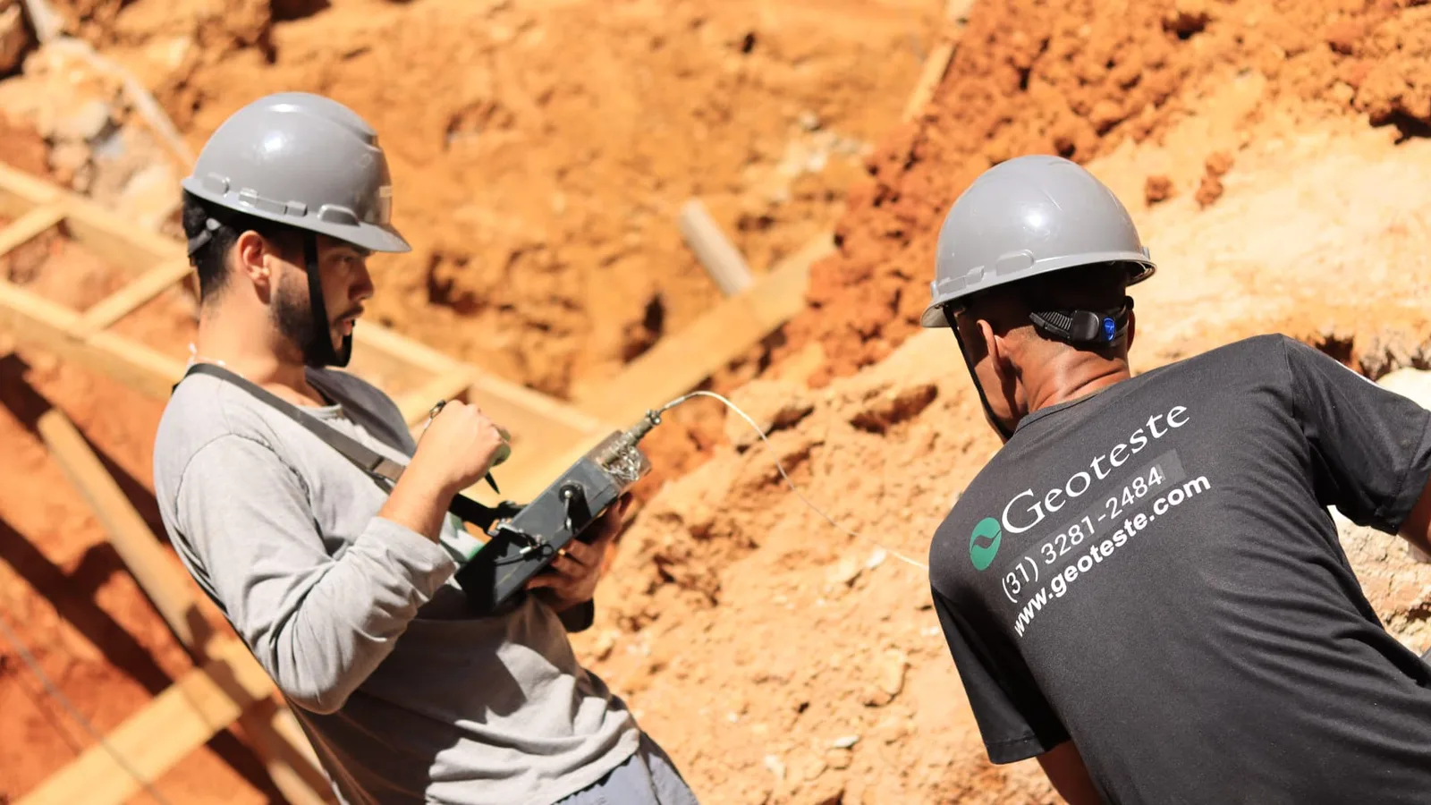
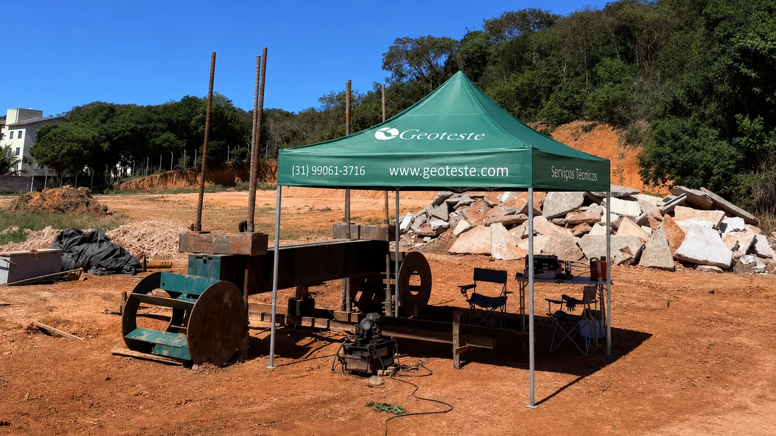
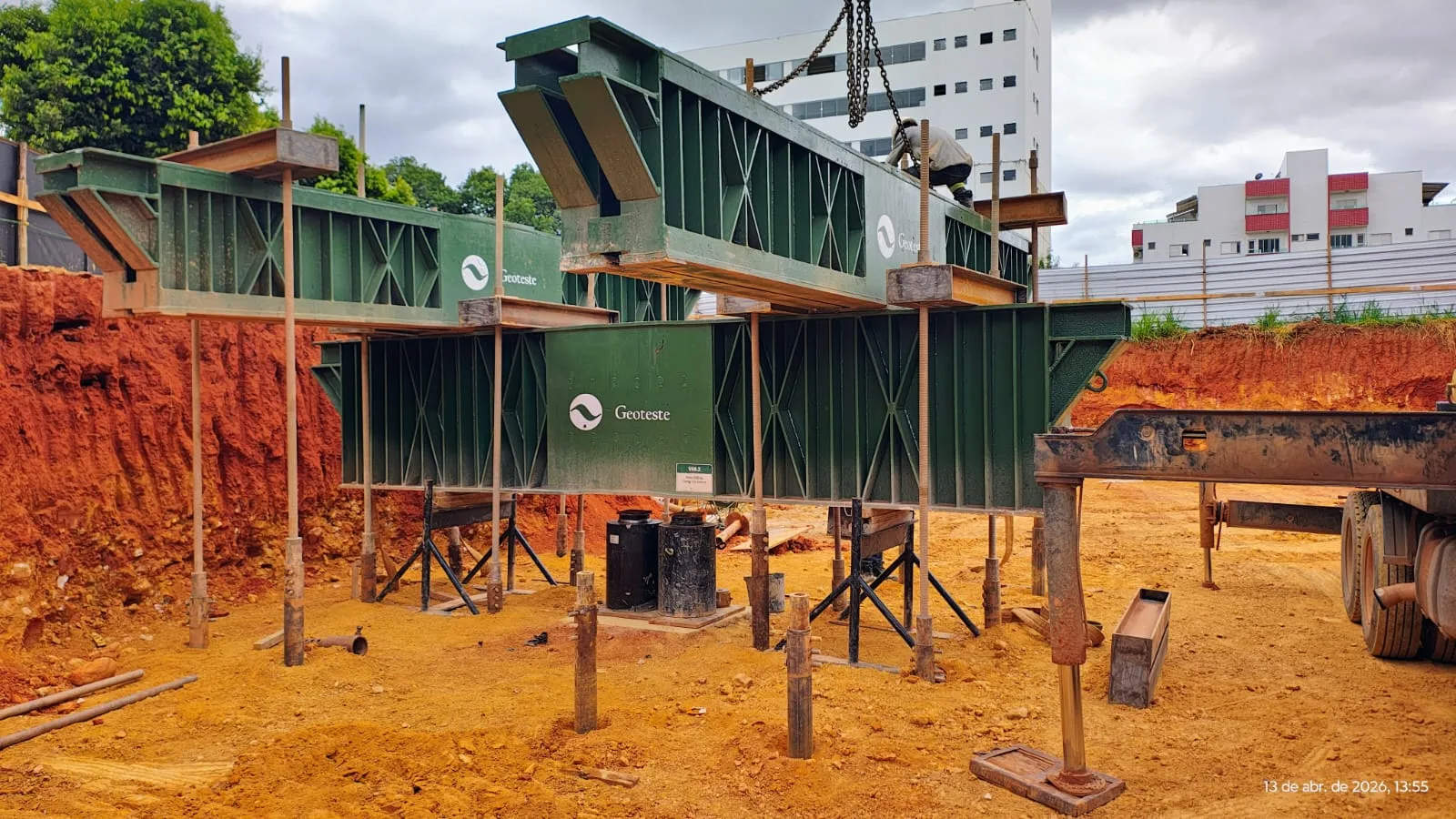
Geoteste performs instrumented static load tests on deep foundations according to the technical criteria of ABNT NBR 16903:2020 and ABNT NBR 6122:2022, providing precise data for characterizing the behavior of bored piles, continuous flight auger (CFA) piles, driven piles, or injected piles. Our technical team works from the instrumentation planning phase, defining the allocation of extensometers, vibrating wire strain gauges, or tell-tales according to the geological profile of the terrain and the structural particularities of the project.
During test execution, we use automated data acquisition systems and continuous calibration of deformability moduli, ensuring the correct separation between load transfer by skin friction and mobilized toe resistance. To obtain specialized support in planning and executing load tests with instrumented piles on your project, please contact the Geoteste technical team.