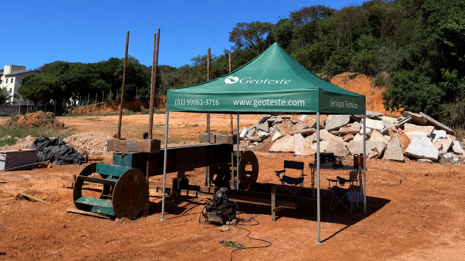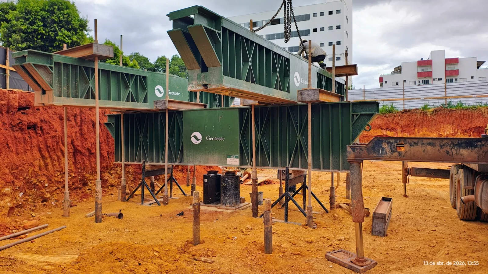
The static load test is the most direct and conclusive method for determining the load versus displacement behavior of a deep foundation element. During the controlled application of axial forces, the field data yield one of the most important graphs in geotechnical engineering: the load x settlement curve. Understanding the trajectory of this graph transcends the simple verification of stability at a given test load. It involves deciphering the mechanics of the interaction between the structural element and the surrounding soil mass.
The correct interpretation of the pile load settlement curve allows for the assessment of fundamental design parameters, the differentiation of lateral friction mobilization from base resistance, the evaluation of the soil and pile system stiffness, and the verification of compliance with ultimate and serviceability limit states. This entire analytical process demands conceptual rigor and adherence to current guidelines, especially ABNT NBR 16903:2020, which governs the execution of tests on deep foundations, and ABNT NBR 6122:2022, which establishes criteria for the design and execution of foundations.
Measured, Calculated, and Estimated Quantities in the Test
Before starting to read the generated curves, the foundation engineer must be clear about the nature of the quantities involved in the test. In a static load test performed in accordance with ABNT NBR 16903:2020, the variables directly measured by calibrated instruments are:
- The force applied at the pile top, controlled by the assembly consisting of a hydraulic actuator, pump, and load cell with a calibrated pressure gauge.
- The vertical displacement of the pile top, recorded by at least four displacement transducers or micrometer deflectometers installed in diametrically opposite quadrants.
- The time elapsed between load increments and throughout each settlement stabilization plateau.
The primary loading curve purely represents the relationship between these physical quantities measured at the top. However, crucial design quantities, such as the division of load between lateral friction and toe resistance along the shaft, the actual ultimate soil resistance, and the purely elastic deformation of the shaft, are quantities calculated or estimated based on mechanical models, subsurface instrumentation, or empirical and semi-empirical extrapolation formulations. Direct measurement from the test should not be confused with mathematical inferences derived from the analysis.
Mechanics of Load Transfer and Resistance Mobilization
The geometric shape described by the pile load settlement curve directly reflects the successive mobilization of two resistant physical mechanisms: lateral friction along the shaft and toe resistance at the base of the element.
Mobilization of Lateral Friction
Lateral friction requires small relative displacements between the pile shaft and the adjacent soil to be fully mobilized. In typical soils, displacements of millimetric order, often between 5 mm and 10 mm, or equivalent fractions of 0.5% to 1% of the shaft diameter, are already sufficient for the friction resistance to reach its peak value or limiting plateau. For this reason, in the initial section of the curve, the response of the assembly is pronouncedly stiff, translated by a steep slope corresponding to the predominant absorption of superficial efforts by the shaft.
Mobilization of Toe Resistance
Unlike lateral friction, toe resistance demands much more significant deformations for its complete mobilization. For the soil beneath the toe to develop its global failure mechanism or plastic punching, settlements between 10% and 25% of the pile base diameter are usually necessary. Consequently, under usual service loads, the toe operates in an incipient elasto-plastic stress regime. This kinematic lag between the peak of lateral friction and the full mobilization of toe resistance explains the characteristic curvilinear shape of the graph, marked by a progressive loss of stiffness as the shaft exhausts its capacity and transfers the remaining load portions to the pile base.
Service Behavior, Residual Settlement, and Load Cycles
ABNT NBR 16903:2020 recommends procedures for continuous loadings or with intermediate and final unloading cycles. The behavior of the curve in the unloading and reloading branches provides valuable insights into the rheological nature of the foundation and soil system.
When the loading reaches the maximum predicted value and the system is unloaded in standardized stages, the pile partially returns to its original position. The recovered displacement corresponds to elastic settlement, comprising the elastic shortening of the structural shaft combined with the resilient recovery of the soil. The permanent displacement that remains after the complete removal of the external load is called residual or plastic settlement.
A pile operating perfectly in a service state exhibits low and proportional residual settlements, demonstrating that the soil under the applied stresses remained predominantly in an elastic regime. The abrupt appearance of large portions of plastic settlement between successive load stages is a clear indication of deep plastification of the soil mass or the onset of exhaustion of the shear strength at the soil-structure interface.
Critical Differentiation: Bearing Capacity, Working Load, and Limit States
In structural and geotechnical design and verification, conceptual confusion between resistance terms can compromise the safety of the building. The interpretation of the load test curve requires strict framing according to the definitions of ABNT NBR 6122:2022:
- Bearing capacity or ultimate resistance: This is the maximum force that the soil and pile assembly supports before manifesting clear physical failure or unacceptable continuous settlements without load increment. It is an Ultimate Limit State (ULS) parameter.
- Allowable load or design resistant force: This is the value obtained by dividing the bearing capacity by prescribed global safety factors, or by applying partial safety weighting coefficients according to the adopted normative approach.
- Working load or service acting force: This is the maximum axial load predicted in the structural design for quasi-permanent or characteristic use combinations, associated with the verification of the Serviceability Limit State (SLS).
SLS performance depends exclusively on the absolute and differential magnitude of the settlements corresponding to the working load, compared with the structural and operational sensitivity of the superstructure. A foundation may have an adequate safety factor against geotechnical failure in the ULS, but exhibit settlements incompatible with tolerances for finishes, enclosures, or sensitive equipment, thus violating the SLS.
Interpretation of Failure and Extrapolation Methods
In most load tests performed in Brazil, the test is interrupted when twice the allowable design load is reached, without the pile reaching actual physical failure in the field. Faced with continuous curves without a clear vertical asymptote, determining the conventional failure load requires the application of criteria and extrapolation methods established in geotechnical literature.
Van der Veen Method (1953)
The analytical method of Van der Veen is based on the hypothesis that the load x settlement curve can be represented by a decreasing exponential function. The method assumes that the accumulated settlement decreases logarithmically as the applied load asymptotically approaches ultimate failure. The model allows for the mathematical determination of the failure load through iterative attempts to adjust the line that linearizes the experimental points.
Chin-Kondner Method (1970)
Chin's method is based on the hyperbolic formulation originally proposed by Kondner for soil behavior. By plotting the ratio between settlement and applied load as a function of the settlement itself on a linear scale, points corresponding to the advanced plastic phase of the test tend to align on a straight line. The inverse of the slope of this line provides an estimate of the ultimate hyperbolic failure load. Because it tends to overestimate the actual bearing capacity when applied to sections that have not yet fully mobilized toe resistance, the criterion should be used with caution by the geotechnical engineer.
ABNT NBR 6122:2022 Criterion
The Brazilian standard ABNT NBR 6122:2022 formally establishes in its normative annex the conceptualization and methodology for determining the conventional failure load when the pile does not reach clear physical failure. The criterion defines the conventional failure load as that which produces a specific settlement at the pile top, calculated by the sum of the elastic deformation of the shaft with a portion of plastic displacement proportional to the pile diameter. This criterion standardizes interpretation, providing an objective and reproducible basis for verifying the safety coefficient of foundations.
Comparison between Ultimate Load Interpretation Methods
The table below summarizes the characteristics, fundamental hypotheses, and pertinent considerations for the analysis methods commonly employed in Brazilian engineering:
| Analysis Method | Mechanical or Mathematical Hypothesis | Primary Applicability | Limitations and Cautions |
|---|---|---|---|
| Van der Veen (1953) | Adjustment by decreasing exponential function with asymptotic approximation. | Driven or bored piles with significant lateral friction mobilization. | Sensitive to the points selected for adjustment, may underestimate late toe contribution. |
| Chin-Kondner (1970) | Hyperbolic relationship between load and settlement in elasto-plastic regime. | Load tests carried to high settlements with onset of plastification. | Tends to overestimate the failure load if applied too early in the friction phase. |
| NBR 6122:2022 Criterion | Definition of limiting displacement summing structural deformation and plastic portion. | Normative standardization for projects executed in Brazilian territory. | Requires precise estimation of the elastic modulus and cross-sectional area of the pile. |
| Décourt Method (1996) | Construction of an auxiliary line relating secant stiffness and applied load. | Verification of large diameter bored piles and continuous flight auger piles. | Requires stable loading plateaus to avoid fluctuations in the stiffness derivative. |
Evaluation of Stiffness and Geotechnical Influencing Factors
The slope of the secant or tangent line to the pile load settlement curve defines the reaction modulus or vertical stiffness of the system for a given stress level. This stiffness is primarily governed by the pile diameter and length, the elastic modulus of the concrete or steel of the structural element, the stratigraphy of the soil mass, and the execution process employed in the foundation installation.
In bored piles with stabilizing fluid, for example, the thickness of residual bentonite at the interface or the accumulation of sediments at the bottom of the bore significantly reduces the initial stiffness and delays the toe response. Conversely, displacement piles compact adjacent granular soils, generating curves with high initial stiffness. Temporal phenomena dependent on pore pressure dissipation, such as consolidation and natural soil aging, also modify the curve behavior if the test is performed prematurely or after long rest periods, highlighting the necessary care when correlating field tests with curing times and geotechnical stabilization.
Geoteste's Contribution to the Execution and Interpretation of Static Load Tests
Reliable execution of a load test and generation of precise curves require advanced technical infrastructure, rigorous sensor calibration, and strict conformity with ABNT NBR 16903:2020 procedures. Failures in the reaction system assembly, misalignments in the hydraulic jack's application axis, or thermal fluctuations in the reference beams introduce severe experimental errors that distort the shape of the pile load settlement curve and lead to erroneous analyses.
Geoteste offers complete support in the execution and interpretation of axial compression, tension static load tests, and instrumented bidirectional tests. Using automated data acquisition systems, high-accuracy electronic transducers, and traceable load cells, Geoteste ensures that field measurements reflect the physical reality of the foundation's behavior. In addition to conducting the test, our technical team assists structural engineers, geotechnical designers, and construction companies in the critical application of ABNT NBR 6122:2022 interpretation methods, enabling engineering decisions based on consistent data for the safe optimization of your enterprise's foundations.
Contact Geoteste specialists to plan your load tests and obtain precise geotechnical analyses for your project.