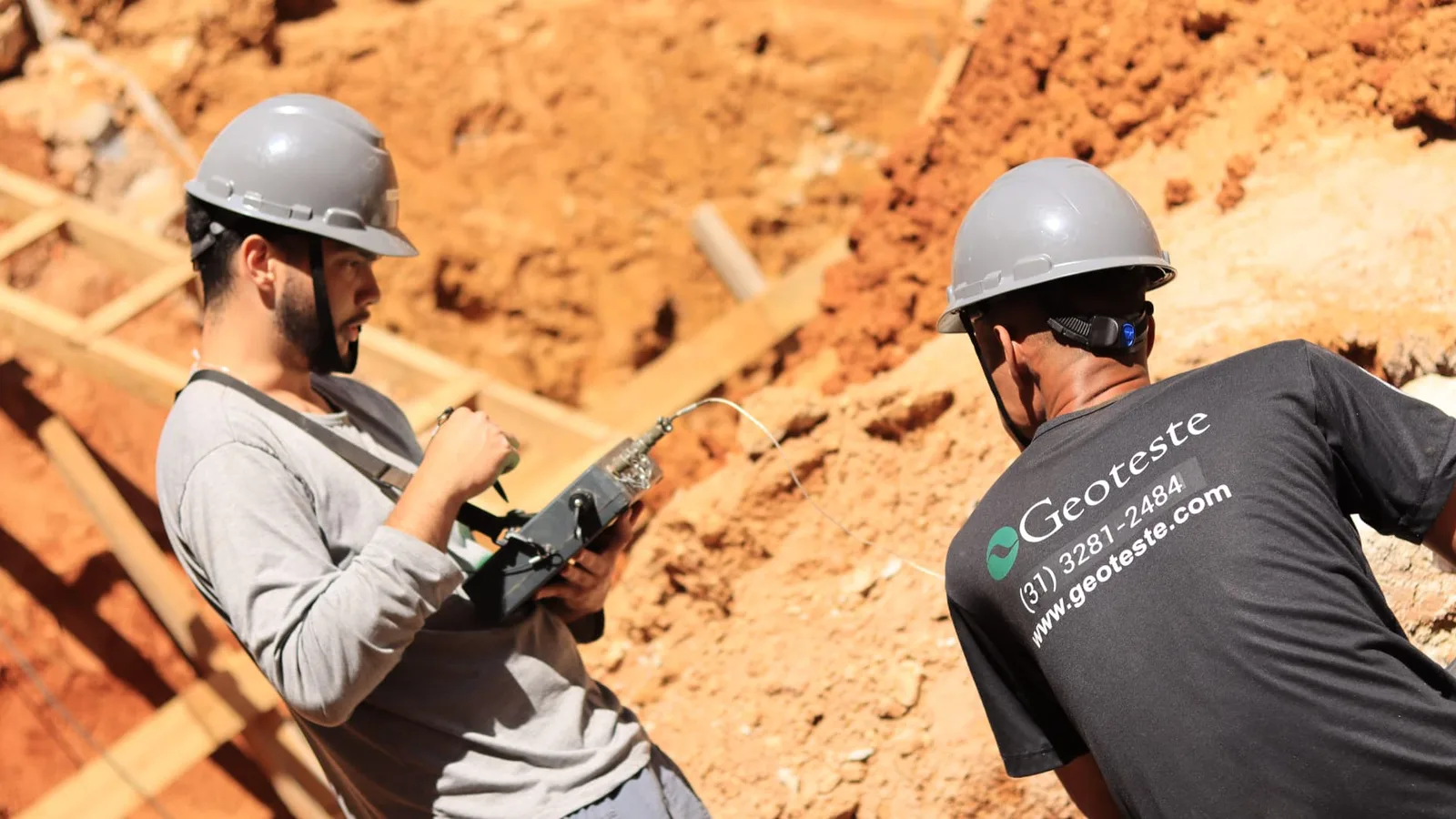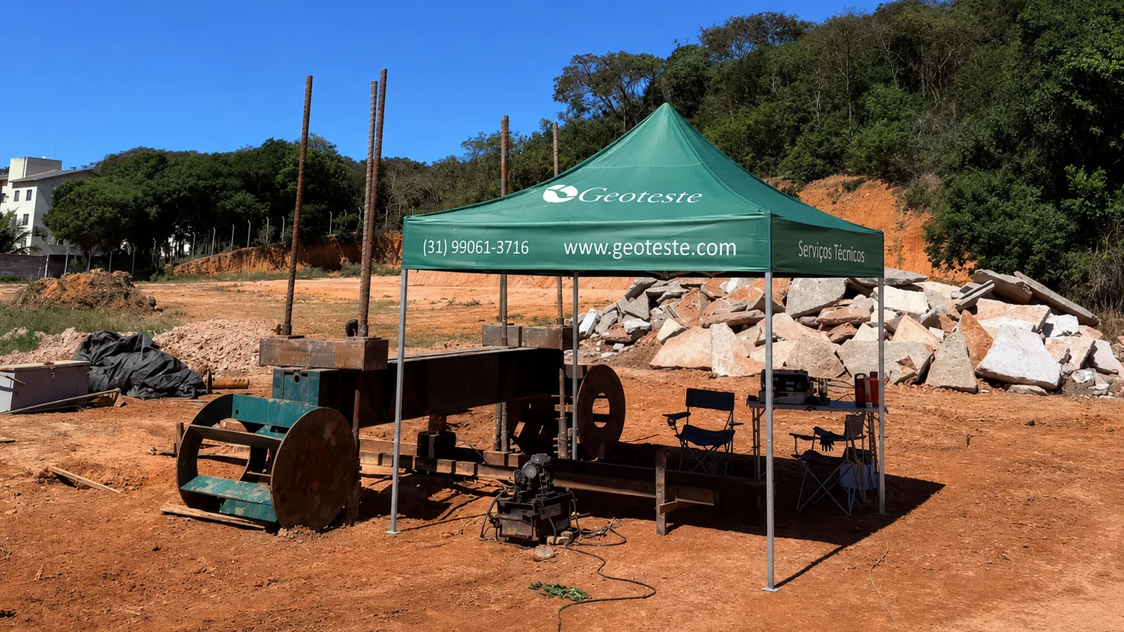
Static load testing on piles (PCE) is the most direct field test to evaluate the load capacity and settlements of deep foundations.
When well-planned, PCE testing allows comparison of the design with the actual behavior of the soil-pile system, reducing geotechnical uncertainties and risks.
Furthermore, static load testing serves as a reference for calibrating semi-empirical methods based on SPT or CPT.
Thus, it holds a central position in foundation engineering guided by performance and systematic quality control.
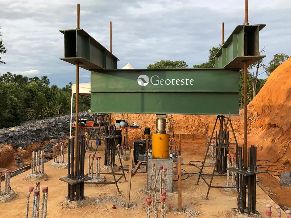
Image 1: Geoteste static load test equipment
1. Basic concepts of static load testing
NBR 6122 (Brazilian Standard 6122) defines that pile resistance can be determined with greater reliability when well-specified and executed static load tests are used.
In this context, static load testing is a full-scale test in which controlled loads are applied and corresponding displacements are measured at the pile head.
Generally, the pile is loaded by hydraulic jacks that react against a stable system, formed by reaction piles, tie-downs, or deadweights.
Throughout the test, the relationship between applied load and measured settlement is recorded, generating the load × settlement curve used in the interpretation.
Finally, static load testing applies to different types of piles, cast-in-place or precast, vertical or inclined, under compression, tension, or lateral loading.
In this way, the same basic concept serves projects from small buildings to industrial and infrastructure works.
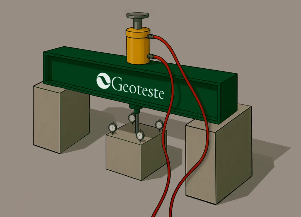
Image 2: PCE test schematic
2. Role of standards and test framework
NBR 6122 addresses the use of static load tests to verify resistance and settlements, both for design and construction control.
NBR 12131, cited in several academic works, establishes the specific test method for static load tests on piles.
According to NBR 6122, when resistance is obtained by static load tests during the design phase, the proof load must reach at least twice the intended allowable load.
Furthermore, the standard allows calculating a characteristic resistance from groups of tests and then applying appropriate partial factors.
The same standard establishes minimum quantities of static load tests based on the total number of piles, the type of element, and the adopted working stresses.
Therefore, PCE testing must be planned from the conception of the piling, and not merely as a subsequent corrective measure.
3. Main types of static load testing
Although the principle is unique, there are different static load test arrangements, suitable for specific objectives.
The most common modalities are:
- Axial compression static load test, which verifies the pile's behavior under downward vertical loading.
- Axial tension static load test, indicated for foundations of towers, silos, and structures subjected to significant upward forces.
- Lateral load static test, used when lateral forces control the design, such as in bridges or port structures.
Additionally, there is the bidirectional test with a hydraulic cell positioned at depth, which allows a clearer separation of the lateral friction and toe resistance components.
In this case, partial curves are combined to obtain a curve equivalent to the conventional top-down test.
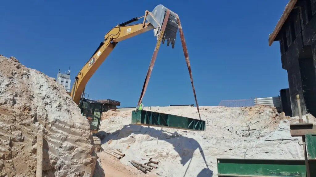
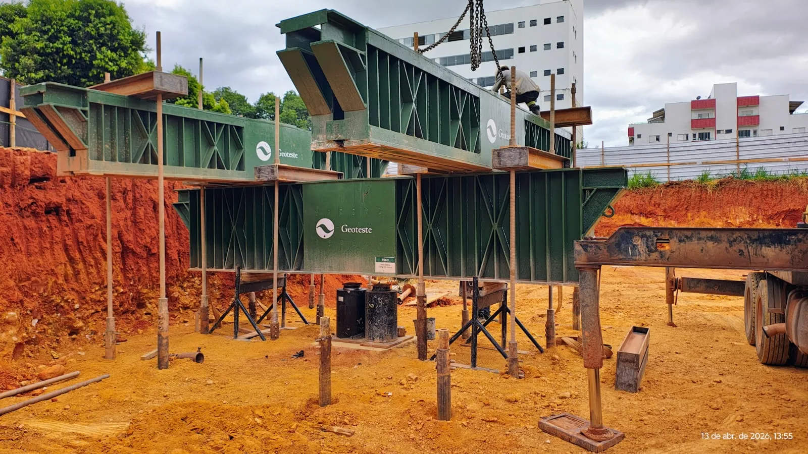
Image 3: Preparation of the structure for PCE testing
4. PCE Test: Planning and objectives
The planning of PCE testing begins with a clear definition of its technical objectives.
Among the most common are the calibration of design parameters, the verification of actual capacity in poorly understood soils, and systematic execution control.
The choice of the test pile should fall on an element representative of the piling, the geotechnical profile, and the execution process.
Ideally, the pile is executed with heightened attention to concreting records, final depth, equipment, and any unforeseen events.
It is also necessary to define beforehand:
- Type of loading: compression, tension, or lateral.
- Loading regime: slow, rapid, or mixed.
- Target maximum load, often associated with a multiple of the design working load.
Finally, planning must include execution deadlines, logistics for transporting beams and equipment, as well as safety conditions on the job site.
5. Reaction system and structural arrangement
The reaction system is the element that ensures equilibrium to the assembly during the test, allowing the applied load to act fully on the tested pile.
Typically, it is composed of metallic or concrete beams supported on reaction piles, tie-downs, or deadweight blocks.
In axial compression PCE, the hydraulic jack is positioned on the pile head, reacting against the beam, which in turn is supported by reaction piles located away from the immediate zone of influence.
In tension tests, the geometry is inverted, and the jack pulls the pile against a reaction frame at an upper level.
Furthermore, the system must have sufficient rigidity so that its own deformations do not significantly interfere with the displacements measured on the test pile.
Therefore, the design of these beams and anchorages is an essential part of the test design, and not a secondary detail.
6. Instrumentation for loads and settlements
From a metrological point of view, the quality of PCE testing directly depends on the load and displacement instrumentation.
The applied load is preferably determined by calibrated load cells, installed between the jack and the reaction system or between the jack and the pile itself.
Hydraulic pressure gauges can be used for redundancy, but they present greater uncertainty and require careful calibration.
Settlements at the pile head are measured with dial gauges or LVDT displacement transducers, supported on independent reference beams, founded outside the influenced zone.
The adoption of at least three or four reading points, distributed around the pile head, allows identifying rotations and obtaining a reliable average value.
In instrumented tests, strain gauges are installed along the pile shaft, allowing precise measurement of the lateral friction and toe resistance components, which are fundamental for analyzing the pile's behavior during loading.
These data are particularly useful for evaluating behavior in stratified soils and for validating numerical models of deep foundations.
7. Loading and unloading sequence
NBR 12131, as cited in several experimental studies, guides loading procedures in successive stages, with settlement readings over time.
The slow loading test is the most classical, characterized by load stages maintained until a condition of near stabilization of displacements.
In practice, the load is applied in typical increments between 10% and 20% of the working load, until the maximum load foreseen in the test is reached.
At each stage, readings are taken at increasing intervals, such as 1, 2, 4, 8, 15, 30, and 60 minutes, until the variation between successive readings is small.
At the end of loading, unloading begins in stages, generally with the same order of magnitude as the increments used during loading.
This unloading allows separating, by comparison, the elastic portion, which recovers, from the plastic portion, which remains as residual settlement.
Besides slow loading, NBR 12131 itself and specialized literature mention rapid loading tests, which use short-duration stages.
In these cases, the total test time is reduced, but the interpretation of settlements requires heightened attention to the viscoelastic characteristics of the soil.
8. Construction of the load x settlement curve
With the raw data of load stages and corresponding displacements, the load × settlement curve, the main result of the PCE test, is constructed.
At the first level of analysis, the settlement values considered stabilized at each load stage are usually used.
The shape of the curve provides clear information about the behavior of the soil-pile system.
When there is a distinct failure, an initial approximately linear section is observed, followed by a sharp change in slope and, sometimes, a plateau of almost constant load with large additional settlements.
In many cases, however, the curve does not have a clearly defined failure, especially for excavated piles in compressible soils and soft clays.
In these scenarios, the geotechnical failure load needs to be estimated by conventional criteria or by curve extrapolation methods.
Furthermore, the unloading curve adds relevant information, allowing evaluation of the elastic stiffness near the working load and the partial reversibility of displacements.
Thus, careful interpretation of the load × settlement curve goes beyond simply seeking a single failure value.
9. Interpretation methods and failure criteria
Technical literature records various methods for interpreting static load test results and defining the failure load of piles.
Among the classic criteria, the following stand out:
- Distinct failure criterion, applicable when the curve clearly shows a plateau, with large settlements without a significant increase in load.
- Conventional failure criterion of NBR 6122, which defines a failure settlement based on the pile's length, cross-section, and elastic modulus.
- Davisson's criterion, which compares the measured curve with a theoretical elastic line plus an additional offset, generally providing a more conservative value.
In addition to these, the following are widely used:
- Chin's hyperbolic method, which adjusts the relationship between settlement and load to a hyperbolic function and obtains failure from the asymptote.
- Brinch Hansen 80% criterion, which defines failure at 80% of the load corresponding to the point of maximum curvature of the load × settlement relationship.
- De Beer's method, which analyzes the curve on a logarithmic scale and identifies changes in deformation regime.
Comparative studies show that different methods can produce significantly different failure loads for the same test, especially when a distinct failure is not achieved.
Therefore, it is always recommended to compare the adopted result with prior knowledge of the subsoil, with the history of the piles, and with the required overall safety.
10. From failure load to allowable load and settlements
Once the geotechnical failure load is defined, this value is transformed into an allowable load or design resistance, according to the adopted design philosophy.
In the allowable stress method, NBR 6122 indicates typical global factors of around 1.6 for resistances obtained by well-conducted static load tests.
In approaches based on design values, a statistically derived characteristic resistance is used, divided by an appropriate partial coefficient, while actions are increased by their own coefficients.
In both cases, the final result must simultaneously meet the ultimate and serviceability limit states, in terms of safety and performance.
Settlement and angular distortion limits are established based on classical studies and accumulated experience, varying according to structural typology and materials used.
Thus, it may happen that the allowable load is limited by settlements or by interaction with neighboring structures, even when geotechnical failure would only be reached at much higher loads.
11. Design PCE vs. Control PCE
It is important to distinguish, in foundation practice, between design load testing and control or performance load testing.
Design load testing is typically performed at the beginning of construction, on a few representative piles, often with more complete instrumentation.
Its objective is to calibrate load capacity predictions, understand the behavior of the local soil, and, if possible, optimize pile lengths and cross-sections.
Control load testing, on the other hand, is carried out during construction, on a minimum percentage of the in-service piles, focusing on verifying that actual performance remains within expectations.
In these tests, the maximum load is usually lower than in the design phase, maintaining safety factors compatible with the importance of the work.
Both types of tests feed into a single performance database, which can support future projects in the same geotechnical region.
Thus, the culture of systematically testing foundations tends to gradually reduce uncertainties and excessive conservatism.
12. Safety, risks, and good practices in PCE testing
Static load tests involve moving heavy loads, high forces, and personnel concentration in a restricted area, which requires rigorous safety planning.
Specific risk analysis studies in PCE identify hazards associated with sudden failure of the reaction system, work at height, and the operation of lifting equipment.
Among the mitigating measures, the following stand out:
- Formal design of the reaction system, with structural and stability verification.
- Isolation of the test area, keeping workers away from the line of action of loads during prolonged readings.
- Training of crane and hydraulic jack operators, as well as rigorous preventive maintenance of equipment.
Furthermore, photographic records, assembly sketches, and detailed test reports promote traceability and future technical auditing.
Therefore, PCE testing should be treated as a complete engineering activity, and not just a mechanical routine of load application. When conducted with this level of rigor, static load testing becomes a strategic tool for designers, contractors, and asset managers, strengthening the reliability of deep foundations throughout the entire service life of the structure.
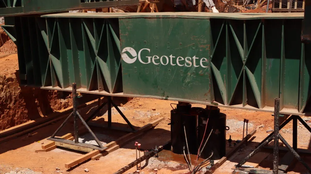
Image 4: PCE Test
Geoteste performs PCE tests throughout Brazil. Consult serviced regions.