Importance of Executive Preparation in Static Load Testing
The static load test, known by the acronym SLT, is the direct and standardized method for evaluating the load versus displacement behavior of deep foundation elements under axial or transverse loadings. However, the reliability of the data obtained and the operational safety of the test fundamentally depend on the stage preceding load application: the preparation of the site, the structural element, and auxiliary systems.
A failure in the preparation of the element head, deficient alignment of the hydraulic jack, or an inadequate reaction system arrangement can induce unforeseen bending moments, premature concrete failure at the pile head, incorrect settlement readings, or even serious accidents on site. Therefore, preparation for static load testing requires rigorous planning, adherence to technical standards, and coordination among designers, contractors, and the geotechnical testing team.
Applicable Technical Standards for Static Testing
The planning and execution of the test in Brazil must follow the prescriptions of current technical standards:
- ABNT NBR 16903:2020: Soil. Static load test on deep foundations. Establishes the test method, instrumentation requirements, load application system assembly, reaction arrangement, and loading execution criteria.
- ABNT NBR 6122:2022: Design and execution of foundations. Defines performance criteria, minimum required test quantities, structural and geotechnical safety requirements, and minimum deadlines for conducting tests.
For projects with international requirements, references such as ASTM D1143/D1143M for axial compression and ISO 22477-1 may be applied as complementary, always respecting national legal and normative requirements.
Preparation of the Pile Head
The pile head, commonly referred to as the pile cap, is the direct transfer point of the load generated by the hydraulic actuator to the shaft. This region experiences high compression stress peaks and must be prepared to withstand stresses higher than those of the rest of the element without localized crushing.
Cut-off and Removal of Defective Concrete
Cast-in-place piles often exhibit concrete of inferior quality or contaminated by soil and stabilizing fluids at the top. The cut-off should be performed with light hand tools or appropriate cutters after preliminary cutting, avoiding the use of heavy hammers that may generate microcracks in the sound shaft below the cut-off level. All fractured material, residual soil, and cement laitance must be removed until sound and homogeneous concrete is reached.
Regularization and Leveling of the Surface
The load application surface must be perfectly flat, horizontal, and orthogonal to the longitudinal axis of the pile. Deviations in flatness or inclination cause eccentric loading on the hydraulic piston, generating bending moments and horizontal components that distort measurements and overload the actuator. Regularization can be done with high-strength mortar, self-leveling non-shrink cementitious grout, or a machined steel plate seated on a thin layer of epoxy resin.
Structural Reinforcement of the Head
For concrete piles, head confinement is mandatory when the test stress approaches or exceeds the characteristic strength of the plain concrete. Reinforcement can be achieved by means of:
- Steel casing: installation of a ring or casing made of rolled steel plate enveloping the pile head, filled with flowable grout.
- Temporary pile cap: execution of a small head block with helical reinforcement or dense stirrups, designed to safely withstand the maximum load anticipated in the test.
- Load distribution plate: a thick structural steel plate positioned between the pile head and the hydraulic cylinder to uniformly distribute the contact stress.
Minimum Deadlines and Geotechnical Variables
The test execution date must consider two essential variables: the curing time of cementitious materials and the stabilization time of the soil around the foundation.
Strength of Structural Materials
The concrete or cement grout of the pile and head reinforcement elements must have reached a strength compatible with the maximum test load, often stipulated as twice the allowable load or working load in load tests to conventional failure. Control can be proven by concrete cylinders molded during concreting and tested for uniaxial compression.
Mass Stabilization and Temporal Effects
Pile installation alters the stress state and generates excess pore pressure in the surrounding soil. The test should not be performed before the dissipation of these pore pressures and the re-establishment of geotechnical conditions. In piles driven into cohesive soils, for example, the gain in strength over time, a process called pile setup, requires waiting intervals defined by ABNT NBR 6122 and the geotechnical designer before loading.
Assembly of the Reaction System
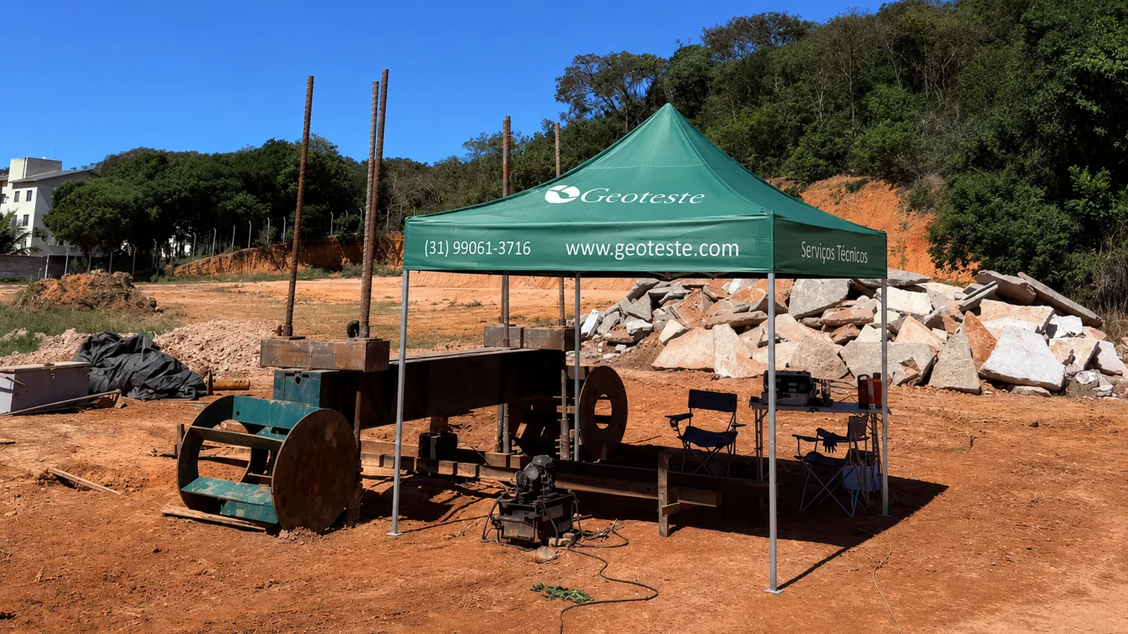
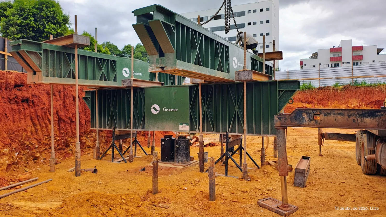
The reaction system provides the static support point against which the hydraulic jack pushes the tested pile. There are two main configurations on the construction site.
Reaction by Tensioned Elements
In this arrangement, highly rigid metallic beams are anchored to adjacent reaction piles, ground anchors, or rock anchors. This is the most frequent system in urban works due to its practicality and smaller space occupied compared to dead weight kentledges.
Reaction by Kentledge
Consists of a platform loaded with concrete blocks, metal ingots, or gravel boxes whose total weight exceeds the maximum test load with a minimum safety margin prescribed by the standard. The system requires temporary support foundations and continuous stability verification against overturning.
Minimum Distances to Avoid Interference
Proximity between the reaction supports and the tested pile can create overlapping stress bulbs, artificially altering the settlement or uplift behavior. ABNT NBR 16903 establishes minimum clear distances between the axis of the test pile and the axes of the reaction piles, anchors, or kentledge supports, respecting geometric limits depending on the element's diameter to ensure the independence of stress bulbs.
Instrumentation and System Alignment
Load and displacement measuring instrumentation must be positioned to eliminate mechanical and thermal interferences during the test.
Reference Beams for Settlement Measurement
The vertical displacements of the pile head are measured relative to reference beams, popularly called reference beams or support frames. These beams must be structurally independent of the tested pile, the reaction system, and the hydraulic pumping system. Their ground supports must be driven or supported at standardized distances from the tested element and reactions, minimizing the transmission of soil deformations to the reference.
Displacement Measurement Devices
Displacement measurement is performed by analog dial gauges or LVDT type electronic transducers. The standard prescribes the installation of at least four sensors arranged in diametrically opposite quadrants on the pile head to record possible rotations and allow the calculation of representative average settlement.
Load Measurement and Calibration
The applied force must be determined by a calibrated load cell positioned in series with the hydraulic actuator or by precision pressure gauges calibrated together with the hydraulic cylinder in an accredited laboratory. The calibration certificate of the pressure gauge, jack, and load cell assembly must be within the validity period.
Checklist for Static Load Test Preparation
The following table consolidates the fundamental steps for releasing the test execution on the construction site:
| Element | Item to Check | Acceptance Criteria |
|---|---|---|
| Pile Head | Integrity and Regularization | Sound concrete, level surface, orthogonal to axis and flat |
| Pile Head | Confinement Reinforcement | Steel casing or reinforced block installed according to design |
| Material Strength | Technological Control | Concrete age compatible and strength reports met |
| Geotechnics | Post-Installation Period | Compliance with minimum curing time and pore pressure dissipation |
| Reaction System | Structural Capacity | Beams and anchors dimensioned for maximum load with safety margin |
| Reaction System | Standard Spacing | Clear distance between supports and pile in conformity with NBR 16903 |
| Instrumentation | Reference Beams | Stable, shaded reference beams fixed outside the zone of influence |
| Instrumentation | Settlement Sensors | Minimum of four diametrically opposite instruments |
| Load Application | Piston Alignment | Jack axis perfectly coincident with pile axis |
| Safety | Isolation Perimeter | Delimited area, unobstructed escape routes and specific PPE |
Safety and Operation Procedures
The static load test mobilizes high forces under high hydraulic pressure. Therefore, the safety routine must be planned before the start of the first loading stage:
- Verification of high-pressure hoses and connections for leaks, cracks, or wear.
- Installation of protections against fragment projection and thermal tarpaulins over the reference beams to mitigate expansion due to solar temperature variation.
- Isolation of the reaction structure's range of action with visible signage, allowing only authorized technical staff to remain in the operating area.
- Definition of a clear immediate shutdown protocol if excessive deformations or noises are detected in the reaction beams, inclination of the hydraulic actuator, or anomalies in readings.
Specialized Technical Support for Static Load Tests
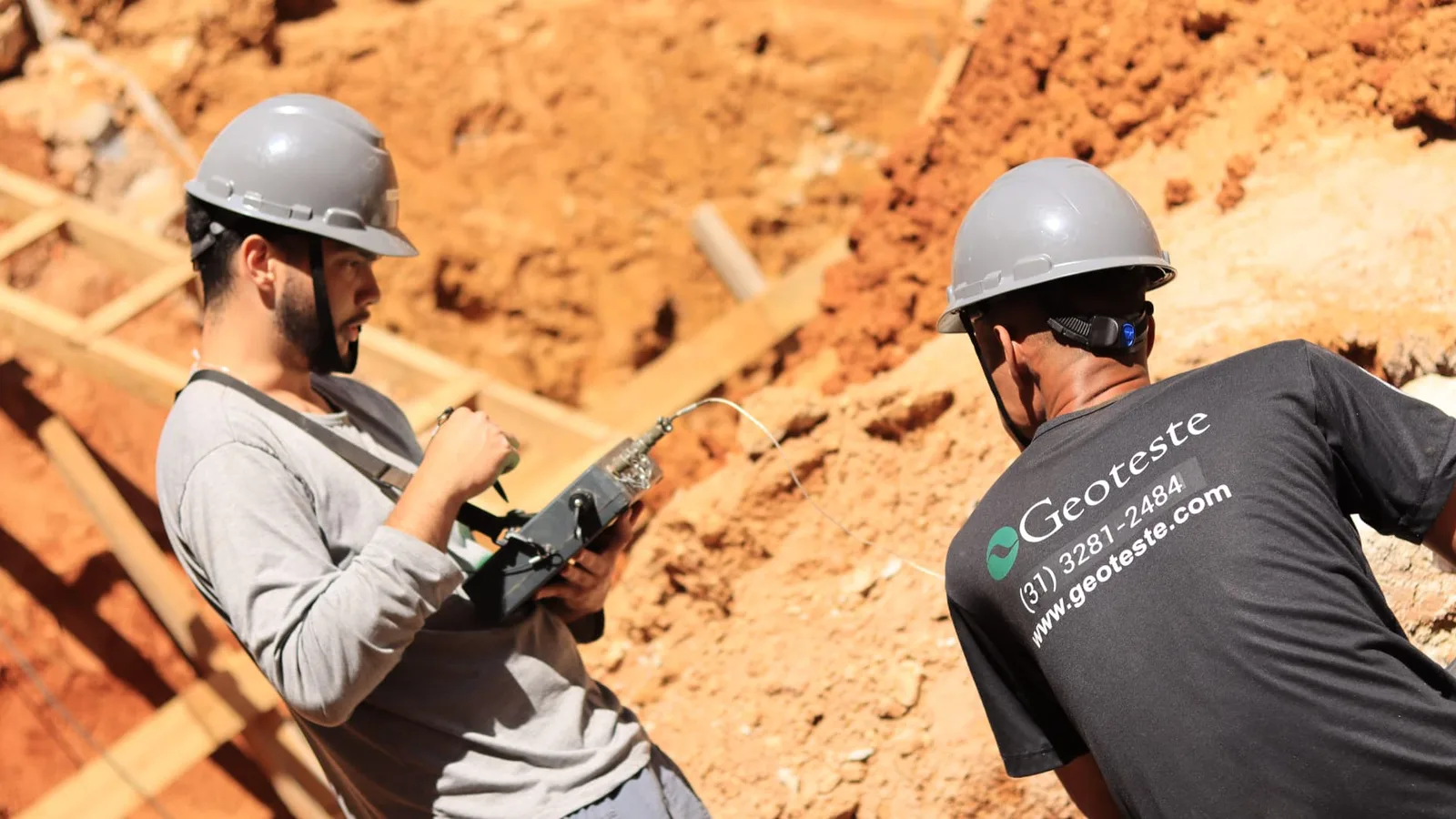
Correct preparation for static load testing is the determining factor for obtaining reliable load versus displacement curves, fully meeting the requirements of ABNT NBR 16903:2020 and ABNT NBR 6122:2022. Geoteste acts in all phases of deep foundation quality control, offering detailed technical support in reaction planning, inspection of structural head preparation, supply of calibrated hydraulic sets, and high-precision instrumentation for static, dynamic, and integrity tests.
To ensure that your load tests are planned with total structural safety, normative compliance, and precision in engineering results, contact the Geoteste technical team and evaluate the ideal solutions for your project.