Introduction to the pullout test
Fundamental concepts and failure modes
What is pullout?
Firstly, pullout refers to the application of an axial tensile load on a pile or tieback. The objective, in this sense, is to mobilize the anchored section in the soil (anchorage bulb) until slippage or rupture occurs. According to NBR 5629, this test determines parameters such as the friction between the soil and the tieback.
What is the purpose of the test?
- To verify if the actual resistance of the anchored section corresponds to the design capacity.
- To validate the design criteria, such as the anchorage length.
- To detect possible execution failures, for example, deficient grout injection.
- To meet normative and contractual requirements for foundation and containment works.
Failure modes in the pullout test
Understanding how an element can fail is crucial. During a pullout test, failure can occur at different points, and identifying where it happened is part of the analysis:
- Failure at the soil-grout interface: This is the most common and desired failure mode in the test, as it allows validation of the soil's lateral friction capacity. It occurs when the anchorage bulb slips relative to the soil mass.
- Failure at the grout-steel interface: Less common, it may indicate problems with adhesion between the tieback's steel bar and the injected cement grout.
- Steel rupture: This happens when the applied load exceeds the tensile strength of the steel itself. It generally indicates that the anchorage capacity in the soil is greater than the structural capacity of the element.
- Failure at the anchorage head: Problems in the post-tensioning system (plates, wedges, nuts) can lead to a localized failure, which does not reflect the capacity of the anchored section.
The execution and interpretation of the pullout test
Generally, the execution and interpretation of the pullout test follow a rigorous sequence, which may vary according to the project, but whose principles of precision are universal.
Planning and preparation
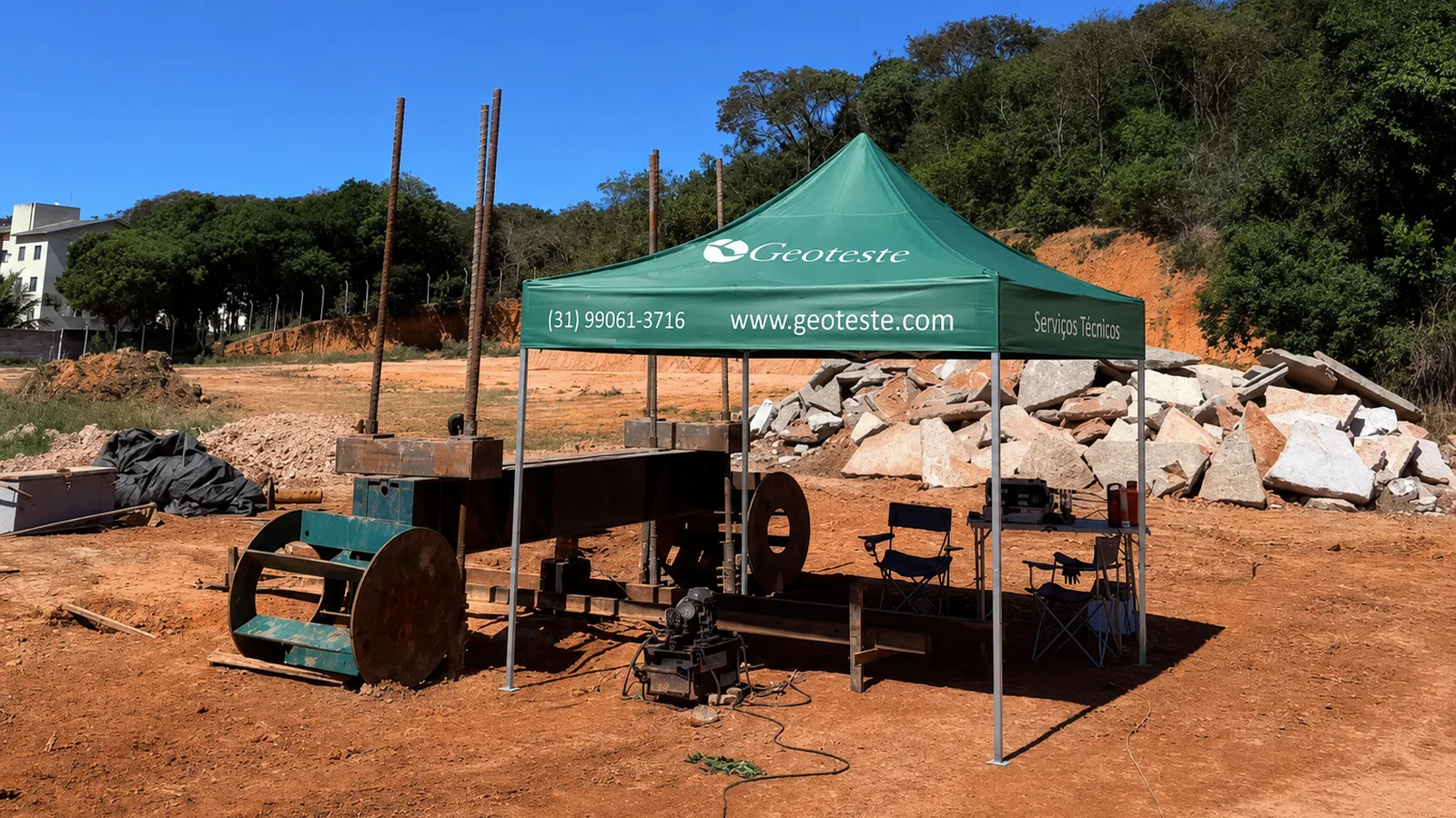
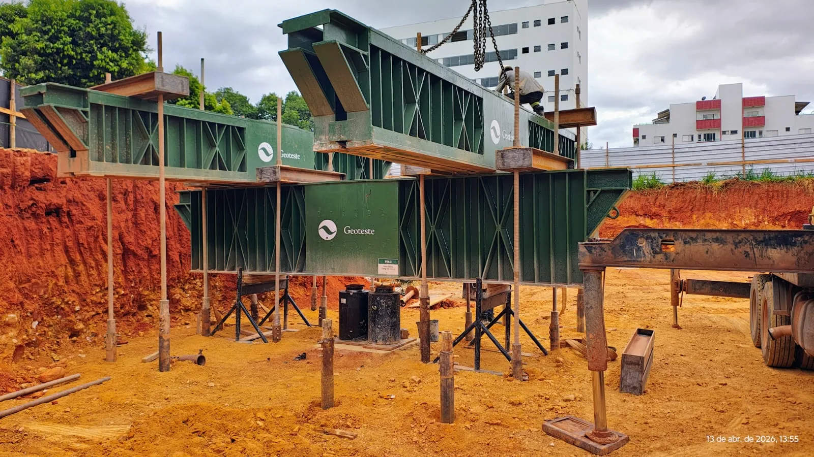
Initial planning involves selecting the pile or tieback to be tested and preparing the logistics of the site. Subsequently, the test setup is a critical point, including the installation of a reaction plate, hydraulic jack, and a calibrated load cell. To measure displacements with the required precision (0.1 mm), the team installs deflectometers with an independent reference beam.
The reaction system: the basis for precision
The reaction system is the structure against which the hydraulic jack applies force. The stiffness of this system is non-negotiable. If the reaction yields or settles during the test, the measured displacements will be a combination of the tieback's movement and the reaction's settlement, masking the actual behavior of the anchorage and invalidating the results. Therefore, robust reaction systems, such as metallic tension frames or the use of properly sized reaction piles, are fundamental.
Load application
The team applies loads in incremental stages, while waiting for displacement stabilization at each step. For tiebacks, for example, NBR 5629 defines different types of tests:
- Type A Test (Qualification): Occurs on 10% of the tiebacks, with a load of up to 1.75 times the working load.
- Type B Test (Acceptance): Is applied to the others, with a load of up to 1.40 times the working load.
Interpretation of the pullout test: the Load vs. Displacement graph
The most important result is, undoubtedly, the graph that relates the applied load (T) to the measured displacement (δ). In effect, the correct interpretation of this curve reveals the behavior of the anchorage:
- Elastic Segment: At the beginning of loading, the relationship is practically linear, and displacements are small and, in general, reversible, indicating the elastic deformation of the steel.
- Onset of Plasticization: The curve begins to lose linearity, indicating that lateral friction is being fully mobilized, and plastic (permanent) deformations begin at the interface with the soil.
- Rupture Plateau: Finally, displacements increase significantly with little or no additional load, defining the maximum capacity. A well-defined curve, without abrupt load drops, generally indicates a ductile rupture at the soil-grout interface. Sudden drops can suggest a brittle rupture or structural problems.
Relevance for designers and contractors
Requiring the performance of pullout tests brings safety and optimization to the project. Furthermore, it offers other benefits:
- Project validation: Confirms that the actual behavior of the anchorage corresponds to theoretical assumptions.
- Risk management: Allows identifying execution or design problems before mass installation.
- Service life guarantee: For permanent tiebacks, creep tests evaluate load loss over time.
Conclusion: an indispensable tool for safety
In short, the pullout test is much more than a normative procedure; it is a high-precision diagnostic tool. It allows the verification of the actual performance of the anchorage, thus contributing to the safety of foundations and containments. Although NBR 5629 provides the guidelines, it is crucial that the contract clearly specifies the tests.
Therefore, to ensure maximum safety in your works, count on Geoteste's expertise in the execution and interpretation of the pullout test, transforming data into safety.