Static Load Test: What does the load × settlement curve really tell us?
Understand the load settlement curve in static load tests, its sections, and how to rigorously evaluate the performance of deep foundations.

Por Rodrigo Gontijo
Engenheiro Civil Geotécnico
CREA/CONFEA 1416959840
What the load versus settlement curve reveals about pile-soil interaction
My civil engineering education at the Federal University of Minas Gerais (UFMG) sparked my early interest in foundation engineering and, primarily, in the possibility of using field measurements to better understand the actual behavior of piles. Throughout my career at Gontijo Fundações, this conviction that geotechnical engineering should integrate design, execution, and monitoring became increasingly evident.
In 1999, at Gontijo Fundações, I developed a project related to the Monitored Franki Pile, in which we sought to control the execution of each pile based on the resistance actually encountered by the equipment during driving. The dimension of the base bulb was not treated simply as a pre-fixed variable: its execution was adjusted according to the characteristics and resistance of the soil identified at each point of the work. In areas of lower resistance, the bulb was enlarged; where the ground showed greater capacity, the procedure was appropriately adjusted. The objective was for piles subjected to the same stresses to exhibit behavior as similar as possible. In practice, this control allowed for a very significant reduction in differential settlements, bringing the foundation closer to a more uniform performance condition.
Almost three decades later, I believe that work already conveyed a principle that has become even more important in contemporary geotechnical engineering: a foundation should not be understood only by its geometry or by the load it theoretically supports, but by how it effectively interacts with the soil and deforms when subjected to stress. It is precisely in this context that the static load test plays a fundamental role. The load versus settlement curve is one of the most valuable records of this interaction and, when correctly interpreted, allows us to see far beyond the simple confirmation of a design load. It reveals the evolution of the pile-soil system's stiffness, the progressive mobilization of skin friction and toe resistance, the emergence of permanent deformations, and the approach of failure mechanisms.
In this article, I seek to explore precisely this interpretation. More than discussing how to perform a load test, the objective is to understand what the load versus settlement curve effectively tells us about the foundation. The same logic that, in 1999, led us to monitor the execution of the Franki Pile to adapt it to real ground conditions remains current: the more reliable information we can obtain about the actual behavior of the foundation, the better our engineering decisions will be, both from a safety and economic perspective, and from the structure's performance.
The static load test is the most established procedure for determining the load versus displacement behavior of a deep foundation element. Far beyond simply certifying whether a pile supports a pre-fixed design load, the test generates a continuous set of records that materializes in the load versus settlement graph. For designers, geotechnical consultants, and field engineers, this curve acts as an X-ray of the mechanical interaction between the structural element and the surrounding soil mass.
The correct interpretation of this behavior requires knowledge of load transfer phenomena, soil mechanics, and current normative requirements, especially ABNT NBR 16903:2020, which governs the execution of static load tests on deep foundations, and ABNT NBR 6122, focused on the design and execution of foundations. Understanding each section of the curve, from the initial loading stages to levels close to failure or the maximum test load, is essential to validate design hypotheses, ensure structural safety, and optimize execution costs.
What is measured and what is interpreted in the test
In geotechnical engineering, the distinction between directly measured variables and interpreted properties is a pillar of technical integrity. During the execution of a static load test, according to the principles of NBR 16903:2020, only three quantities are directly measured at the pile top: the load applied by the hydraulic jack and load cell assembly, the vertical displacements recorded by electronic sensors or deflectometers, and the time elapsed in each loading or unloading stage.
All other geotechnical understanding depends on calculation, deduction, and constitutive models. Ultimate geotechnical bearing capacity, soil failure at the base, or the exact division between skin friction and toe resistance are not directly measured at the top, unless the pile receives instrumentation at depth through strain gauges or extensometers along the shaft. When instrumentation is exclusively at the top, the separation of resistance mechanisms and the establishment of physical or conventional failure parameters are the result of a reasoned interpretation of the load versus settlement curve.
Anatomy of the load versus settlement curve
The resulting plot from an axial compression loading reflects combined responses of the deformability of the pile material (concrete, steel, or timber) and the deformability of the soil. Didactically, a complete conventional load test curve up to high stress levels presents three distinct phases of mechanical behavior.
Initial section and linear elastic behavior
In the initial loading phases, with low to moderate values of applied axial force, a predominantly linear response between load and top settlement is observed. In this phase, most of the measured displacement corresponds to the elastic shortening of the foundation element itself and elastic deformations of the soil at very low shear levels.
It is at this initial stage that skin friction along the shaft begins to be mobilized from the top towards the deeper layers. Requiring very small relative displacements to reach its limit stress, the soil-shaft interface assumes almost the entirety of the resistance in the initial stages, causing little or no stress to reach the pile toe.
Transition section and progressive plastification
As the load approaches and exceeds the design working load, the curve's inclination begins to change significantly. Linearity gives way to a gradual loss of stiffness of the pile-soil system. This parabolic or sharply curved section marks the progressive plastification of the soil-shaft interface, starting at the top and gradually migrating to the lower elevations.
In this phase, the available skin friction in the shaft reaches its exhaustion point in the upper layers. The additional applied load can no longer be fully absorbed by the already plastified friction and is gradually transferred to the deeper portions of the pile and, finally, to the toe. The increase in the settlement rate per load increment indicates that the adjacent soil has reached high levels of shear deformation.
Plastic section and asymptotic approach
When the resistance capacity due to skin friction along the entire shaft is fully developed, any supplementary loading must be supported by the toe or base resistance of the pile. The curve then assumes a very pronounced inclination relative to the vertical displacement axis, approaching a vertical asymptote or maintaining a constant and reduced inclination.
For piles that work predominantly by skin friction, known as floating piles, the curve frequently shows a clear horizontalization, characterizing an abrupt or continuous shear failure of the soil. For piles founded on competent layers or toe on rock, even after complete plastification of the shaft, the toe continues to offer additional support, generating an inclined line that depends directly on the stiffness and bearing capacity of the basal mass.
Kinematic mobilization: shaft versus base
One of the most relevant lessons learned from the analysis of the load versus settlement curve is the disparity of displacements required to mobilize the two resisting components of a deep foundation.
Geotechnical studies and empirical observations demonstrate that skin friction resistance is mobilized with relatively small relative displacements between the pile and the soil mass. In general, top settlements between 1 and 5 millimeters, rarely exceeding 10 millimeters, are sufficient for skin friction to reach its maximum value, regardless of the pile diameter.
In contrast, the full mobilization of toe resistance requires a much more severe kinematic mechanism. The foundation base requires vertical displacements on the order of 5% to 15%, and in some soils up to 20%, of the pile diameter for the failure wedge to fully form and reach the ultimate bearing capacity. For this reason, in load tests interrupted by reaction system limitations without deep instrumentation, it is common for the toe to have mobilized only a modest fraction of its maximum capacity.
Criteria for interpreting failure and geotechnical capacity
Rarely does a pile in soil reach an obvious physical failure during a static load test, where settlements increase indefinitely without any increase in force. More commonly, the test reaches the reaction capacity of the anchorage steel structure or is interrupted upon reaching twice the design working load, as required by NBR 6122.
Given the absence of clear physical failure, technical literature and standards establish criteria to define conventional failure or to extrapolate the obtained curve and estimate the ultimate load of the element.
Interpretation Method | Operational Principle | Preferred Application | Main Limitation |
|---|---|---|---|
Van der Veen (1953) | Exponential curve fitting assuming asymptotic growth of settlements. | Driven or bored piles with predominant skin friction. | Tends to underestimate capacity in large diameter piles with significant toe resistance. |
Davisson (1972) | Drawing a line parallel to the pile's elastic line with a compensation displacement. | Precast concrete driven piles, steel sections, and rails. | Can be excessively conservative for larger diameter bored piles. |
Chin-Kondner (1970) | Hyperbolic relation linearizing the settlement per load ratio as a function of settlement. | Piles with well-developed curves and considerable settlements. | Risk of overestimating ultimate load if the curve has not reached an advanced stage. |
ABNT NBR 6122 Criterion | Definition of conventional failure based on elastic deformation plus a portion of toe displacement. | Projects subject to Brazilian technical regulations for foundations. | Requires precise data on the modulus of elasticity and actual cross-sectional area of the element. |
The adoption of any of these interpretation methods must be done with careful geotechnical judgment. The calculated estimate by a mathematical model should not be confused with the element's actual ultimate capacity if the test has not reached displacement levels compatible with the proposed model.
Elastic behavior and residual settlement in unloading cycles
Static load test procedures performed according to ABNT NBR 16903 include intermediate and final unloading stages. The analysis of the unloading branch on the Cartesian plane provides essential information about the distribution between reversible and permanent deformations.
The total settlement recorded at peak load is divided into two parts:
Elastic or recoverable settlement: the fraction of displacement that the pile recovers when returning to zero load, composed of the elastic shortening of the pile's structural material and the elastic deformation of the surrounding soil.
Plastic or residual settlement: permanent, unrecovered deformation resulting from irreversible soil shearing, rearrangement of granular particles, and eventual plastification at the toe or shaft interface.
The comparison between the theoretical elastic deformation calculated by elementary mechanical principles and the actual recovery observed during unloading allows for checking the structural integrity of the shaft. If the elastic recovery is substantially less than the theoretical deformation expected for the pile's length, this may indicate that skin friction retained structural deformation due to residual stresses, or it may point to eventual discontinuities in the concrete.
Influence of time and executive methodology of the test
The mechanical response observed in the curve also depends on the test method adopted. ABNT NBR 16903 establishes two main procedures for applying load stages:
Slow Maintained Load (SML): each load stage is maintained until complete stabilization of settlements, meeting normative criteria for residual displacement velocity. It is the reference method for characterizing deformations under long-duration loads.
Quick Maintained Load (QML): load stages are maintained for fixed, reduced time intervals, regardless of full stabilization. This procedure allows for determining the curve in shorter periods, being widely used for quality control and statistical calibration.
In addition to the loading rate, the time elapsed between foundation installation and test execution plays a decisive role in the result. In saturated cohesive soils, for example, the installation of driven piles generates substantial excess pore pressure. A load test performed without sufficient time for these pressures to dissipate will register a curve with lower stiffness and less mobilized resistance.
Similarly, temporal phenomena such as the temporal gain in pile capacity, internationally known as pile setup, resulting from the aging and reconsolidation of the soil, can drastically alter the position and inclination of the curve if tests are performed at different ages after driving or boring.
Interpretation of load tests with Geoteste's support
The correct interpretation of the load versus settlement curve is not merely a bureaucratic construction step, but the central element for ratifying deep foundation design decisions. Through it, designers can confirm the global safety factors prescribed by NBR 6122, ascertain the actual deformation moduli of the soil mass, and support safe and economical engineering solutions.
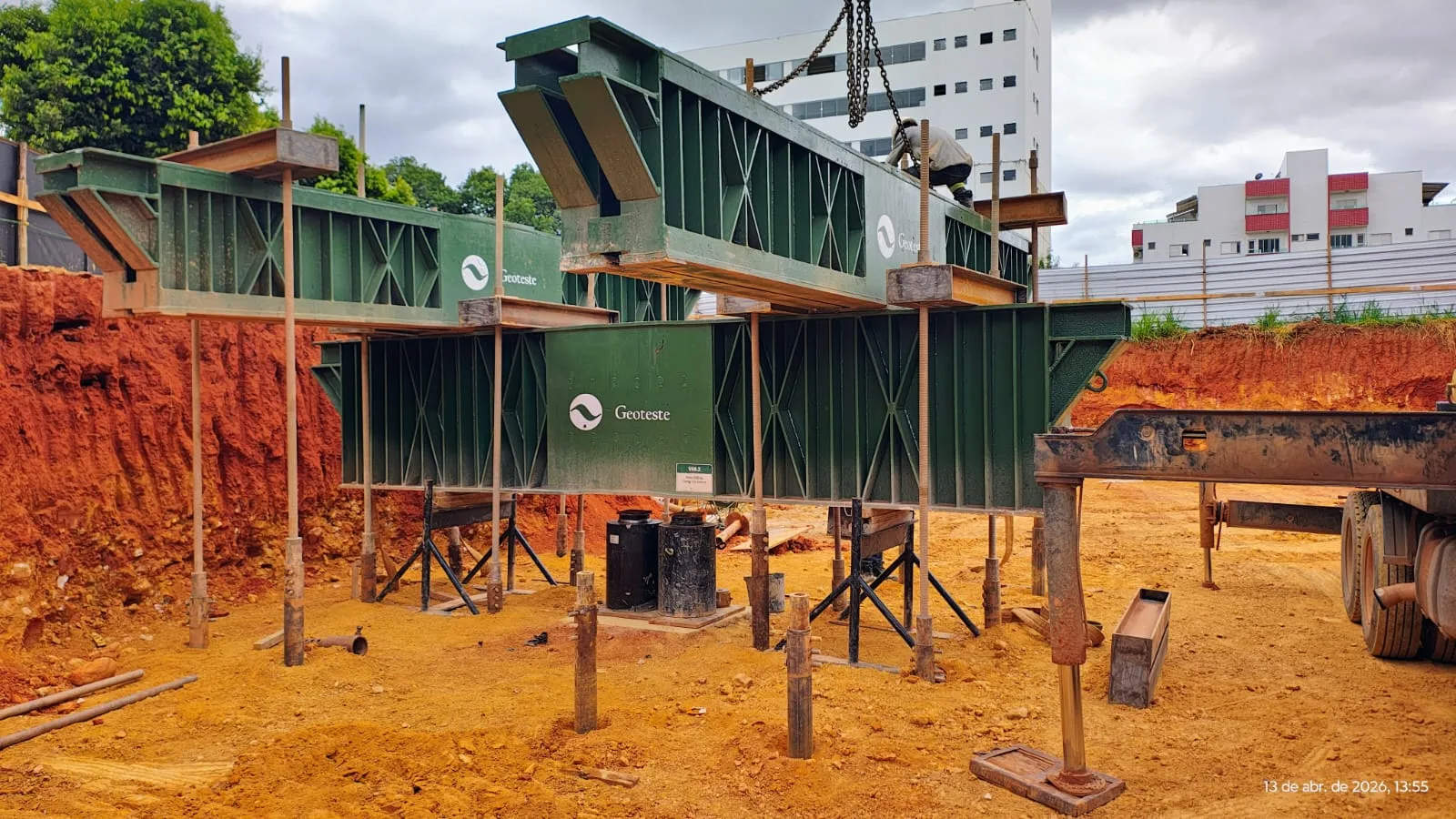
Geoteste acts in all stages of static load tests on deep foundations, performing tests in full compliance with the requirements of ABNT NBR 16903:2020 and providing technical advice for the consolidation of analytical reports on structural and geotechnical performance. Our team mobilizes calibrated hydraulic sets, reaction systems dimensioned for high capacities, high-precision electronic instrumentation, and continuous data acquisition from the top and shaft, ensuring reliable data for the interpretation of bored piles, driven piles, continuous flight auger piles, and caissons. Contact our specialists for specialized technical support in validating your project's foundations.