The characterization of the load versus displacement behavior of deep foundation elements is an essential step for validating geotechnical design hypotheses. Among the direct investigation methods, the static load test has consolidated its position as the most conclusive test for determining the mechanical behavior and bearing capacity of the buried structural element. However, applying high loads to a test pile requires a structurally safe reaction system, dimensionally compatible with the construction site, and economically viable.
Traditionally, performing an axial compression load test relies on large dead weight boxes or tensioned reaction piles, such as bored piles or injected metallic profiles. In densely occupied urban sites, operational industrial areas, or terrains with severe logistical limitations, the assembly of these conventional structures can be complex and costly. In this scenario, the static load test with helical reactions emerges as a highly efficient engineering solution, combining executive speed, high tensile anchorage capacity, and environmental sustainability.
The challenge of reaction systems in load tests
The static compression load test requires the hydraulic jack, positioned on top of the tested pile, to push the foundation downwards while reacting against a resistant suspended structure. For the loading to reach the intensity specified in the standard, the reaction system must be able to comfortably support the maximum test load, without showing excessive deformations or geotechnical failure due to tension.
The use of load boxes filled with concrete blocks, steel ingots, or gravel bags imposes severe logistical challenges. It requires constant heavy transport, large cranes, flat and stable areas for grid leg support, and extended assembly and disassembly times. Furthermore, the presence of an overburden of tens or hundreds of tons very close to the test pile can alter the stress state in the shallow soil, potentially interfering with settlement measurements.
On the other hand, the use of conventional cast-in-place concrete piles as tension reaction elements requires concrete curing time, which postpones the execution of the test. In addition, such piles remain permanently in the ground after the test, creating subterranean interferences for future interventions on the site. Helical anchoring solves most of these operational restrictions by dispensing with cementitious materials and enabling the reuse of elements.
Principles of static load testing with helical reactions
Helical piles consist of a central steel shaft, tubular or solid, to which helical plates with carefully calculated geometry and pitch are welded. The element is installed in the ground by continuous torque applied by hydraulic motors coupled to excavators or dedicated drilling rigs, advancing into the soil similar to a screw.
When subjected to tension during the compression test of the test pile, helical piles mobilize the shear resistance of the soil mass through their metallic helices. Depending on the relative spacing between the helices along the shaft, the failure mechanism can occur by the individual action of each plate or by the formation of a continuous shear cylinder of soil between the extreme plates.
Among the most advantageous characteristics of helical reactions is the direct correlation between the installation torque recorded at the drilling head and the mobilizable tensile load capacity of the element. This particularity allows the geotechnical engineer to verify, in real time during drilling, whether the achieved depth and the final torque are sufficient to absorb the test load required by the project, providing high predictability of performance to the structural arrangement.
Normative requirements and minimum interference distances
The performance of static load tests on deep foundations in Brazil is regulated by ABNT NBR 16903:2020 (Soil: Static load test on deep foundations), a document that replaced the old NBR 12131. The general guidelines for design, project criteria, and minimum number of tests in foundation works are determined by ABNT NBR 6122:2022 (Design and execution of foundations). Internationally, the method is supported by consolidated references such as ASTM D1143/D1143M for compression and ASTM D3689/D3689M for axially tensioned elements.
One of the most critical aspects in planning the static load test with helical reactions is the control of geometric and geotechnical interferences. ABNT NBR 16903:2020 establishes strict requirements for the spacing between the test pile and the reaction anchor points. The objective is to ensure that the tension stress bulb developed by the helices does not interfere with the shaft or the toe of the pile being compressed.
According to normative precepts, the clear distance between the face of the test pile and the face of any reaction element must be established based on the following technical guidelines:
- The center-to-center distance between the tested pile and the helical anchor points must be at least three times the diameter of the largest pile, respecting a recommended absolute minimum clear distance of two meters.
- The anchoring depth of the helices must be planned to prevent uplift failure planes from intercepting the lower load transfer portion of the test pile shaft.
- The supports of the reference beams that hold the dial gauges or displacement transducers must not be influenced by deformations caused by the reaction piles, and must be positioned at a minimum distance of three diameters from the tested element or the reactions.
Assembly of the structural arrangement and measurement instrumentation
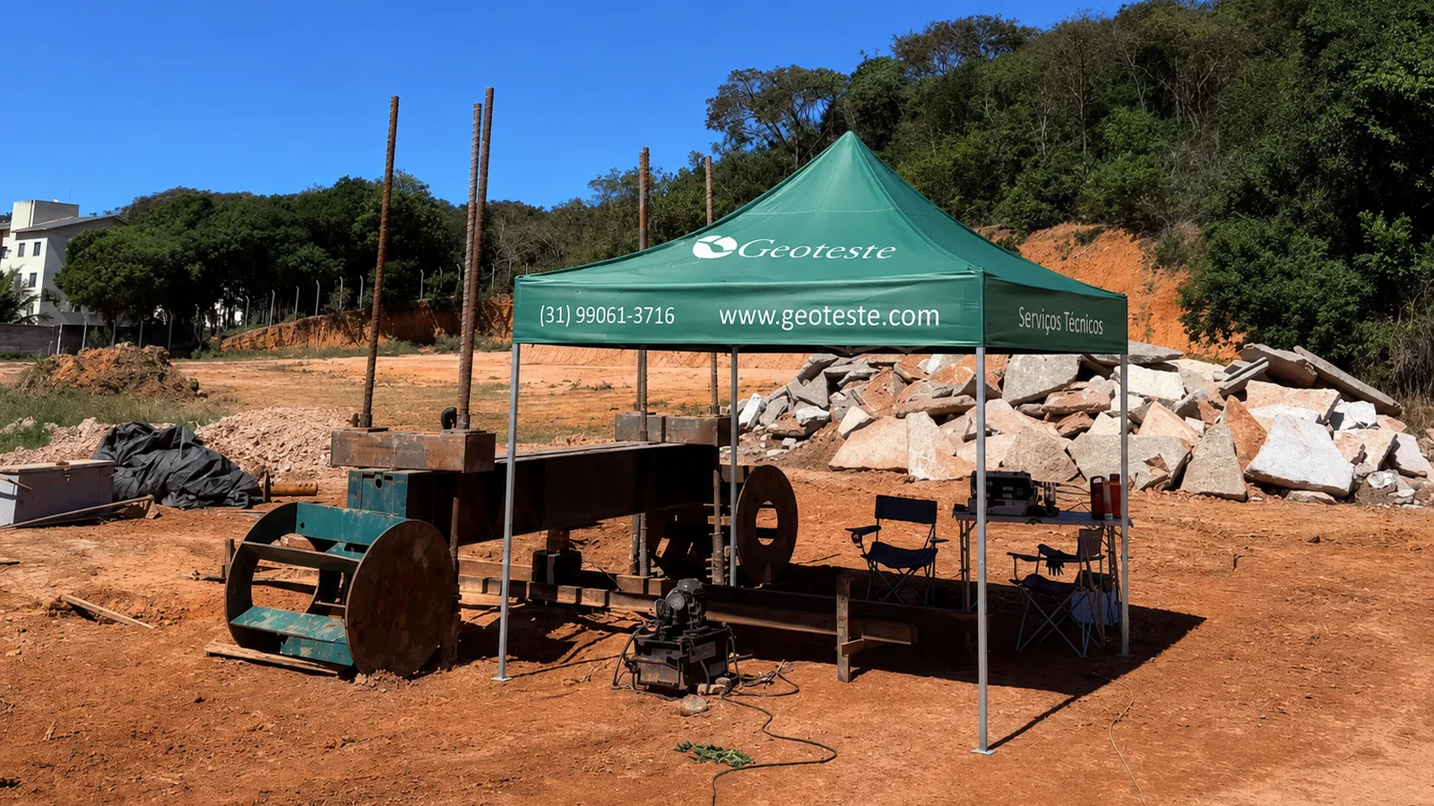
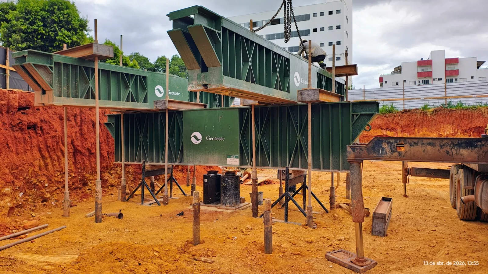
The mechanical assembly of the helical reaction system requires precision and structural rigor. The set of anchorages is connected by rolled or welded steel beams, dimensioned to resist the bending moments, shear forces, and contact stresses generated during the application of the stipulated maximum load.
The hydraulic jack is centered on the bearing plate at the top of the test pile. Between the jack and the main reaction beam, a load cell, properly calibrated in an accredited laboratory, is positioned, operating in conjunction with a digital or analog control manometer. The load is applied in stages predefined by the test plan, which can follow the slow or rapid loading procedure according to the normative specifications of ABNT NBR 16903:2020.
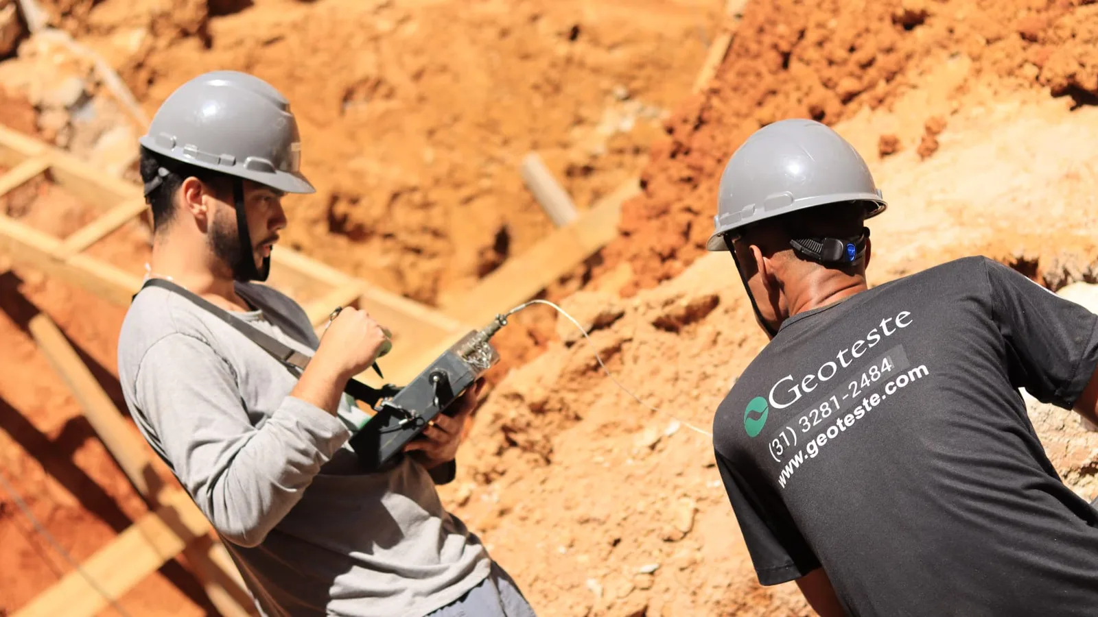
The measurement of vertical displacements at the top of the pile is performed using at least four linear inductive displacement transducers (LVDT) or dial gauges with a minimum resolution of hundredths of a millimeter, arranged diametrically opposite at a ninety-degree angle. These instruments are fixed on reference beams structurally isolated from the test pile, the reaction beam, and site traffic, ensuring measurements free from external influences.
The instrumented pile and the detailing of geotechnical behavior
In larger projects or works with foundations subject to complex demands, the static load test with helical reactions is often executed in conjunction with an instrumented pile along the shaft. The combination of these two technologies raises the level of understanding of foundation performance.
While the traditional test measures exclusively the load and settlement curve at the top of the pile, the instrumented pile allows quantifying load transfer at depth. Through duly calibrated sensors fixed to the reinforcement or embedded in the concrete, such as electrical resistance strain gauges, stress cells, or mechanical extensometer bars (telltales), it is possible to isolate two fundamental variables:
- The actual distribution of lateral friction along the different stratigraphic layers traversed by the shaft.
- The portion of load effectively transmitted to the pile toe and the stiffness of the underlying bearing soil.
Monitoring an instrumented pile subjected to helical reaction offers high-fidelity data for back-analysis of soil mass strength and deformability parameters. With this information in hand, the designer can optimize the length of the production piles of the work, reducing executive costs with full experimental support and conformity with the performance guidelines of ABNT NBR 6122:2022.
Operational advantages of the helical anchoring system
The use of helical elements to provide reaction in load tests offers direct operational benefits for construction companies and project managers:
- Immediate testing: as helical piles work purely by mechanical engagement and shearing of the soil in contact with the steel blades, there is no need to wait for cement grout or concrete curing times. Once installed, the reactions are ready to be subjected to tensile stress.
- Reduced site occupation: the arrangement requires a minimal interference area compared to the wide base needed to stack hundreds of tons of blocks in conventional load boxes.
- Total removal and sustainability: after the test is concluded, the helical piles can be unscrewed and completely removed from the subsoil with the same equipment used for installation, leaving no buried structural liabilities on the lot and allowing the reuse of metallic modules in new tests.
- Continuous monitoring: continuous measurement of torque during insertion acts as a preliminary quality control of the uplift capacity of each anchoring element.
Geotechnical limitations and good execution practices
Despite its remarkable versatility, the use of helical reactions requires careful prior analysis of the geotechnical profile resulting from simple reconnaissance borings (SPT) or cone penetration tests (CPT). The presence of boulders, thick horizons of compact gravels, demolition concrete fragments, or slightly fractured rocks at shallow depths can make the penetration of metallic helices impossible without structural damage to the shaft.
Furthermore, during the execution of the test, it is mandatory to monitor the vertical top displacements of the helical reaction piles themselves. This care ensures that the anchoring elements do not exceed the elastic deformability limits of the steel or reach geotechnical failure by uplift, preserving the horizontality of the reaction beams and avoiding undesirable eccentricities of loading on the hydraulic piston.
Specialized execution of load tests with Geoteste
Geoteste offers complete and customized solutions for performing static load tests with helical reactions, strictly adhering to the technical guidelines of ABNT NBR 16903:2020 and ABNT NBR 6122:2022. Our work includes everything from preliminary geotechnical analysis for sizing the reaction arrangement to the supply of structural transition beams, calibrated jacks, automated data acquisition systems, and advanced instrumentation for instrumented piles.
With an experienced technical team and modern equipment, Geoteste operates in all phases of deep foundation quality control, ensuring safe, fast, and reliable tests to support design decisions and constructive optimization. Contact Geoteste's engineering team to structure the ideal solution for your project's load tests.