The role of the static load test in foundation engineering
The static pile load test represents the most direct and conclusive method for determining the mechanical behavior of the interaction between the foundation element and the surrounding soil mass. Unlike empirical estimates based on field investigations or indirect dynamic tests, this deep foundation test applies axial loads in a controlled manner, directly measuring the corresponding displacements at the top of the tested element.
Performing the static load test, known by the acronym PCE estaca (PCE pile), allows verifying performance under service loads, assessing the stiffness of the soil-foundation system, and quantifying the ultimate geotechnical bearing capacity when the test is carried to failure or to loads substantially higher than the design load. It is an indispensable tool for validating design hypotheses, verifying executive methods, and reducing geotechnical uncertainties in medium to large-scale structural projects.
Applicable standards and fundamental technical requirements
The execution and evaluation of results from an axial load test on deep foundations require a rigorous distinction between the standard that establishes the executive method of the test and the standard that regulates the design and acceptance criteria of the work.
The test procedure in Brazil is fully governed by ABNT NBR 16903:2020 (Soil: Static load test on deep foundations), a technical standard that replaced the old NBR 12131. NBR 16903 establishes the requirements for apparatus, setup, settlement stabilization, instrument calibration, loading cycles, and report presentation. It standardizes how applied load, time, and displacements must be monitored.
Complementarily, ABNT NBR 6122:2022 (Design and execution of foundations) defines the general design guidelines, the conditions under which the test becomes mandatory, the safety factors or reduction coefficients to be adopted, and the conceptual criteria for determining the allowable load or design resistance based on the results obtained in the field.
Components and setup of the test system
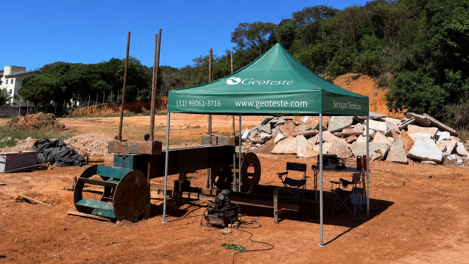
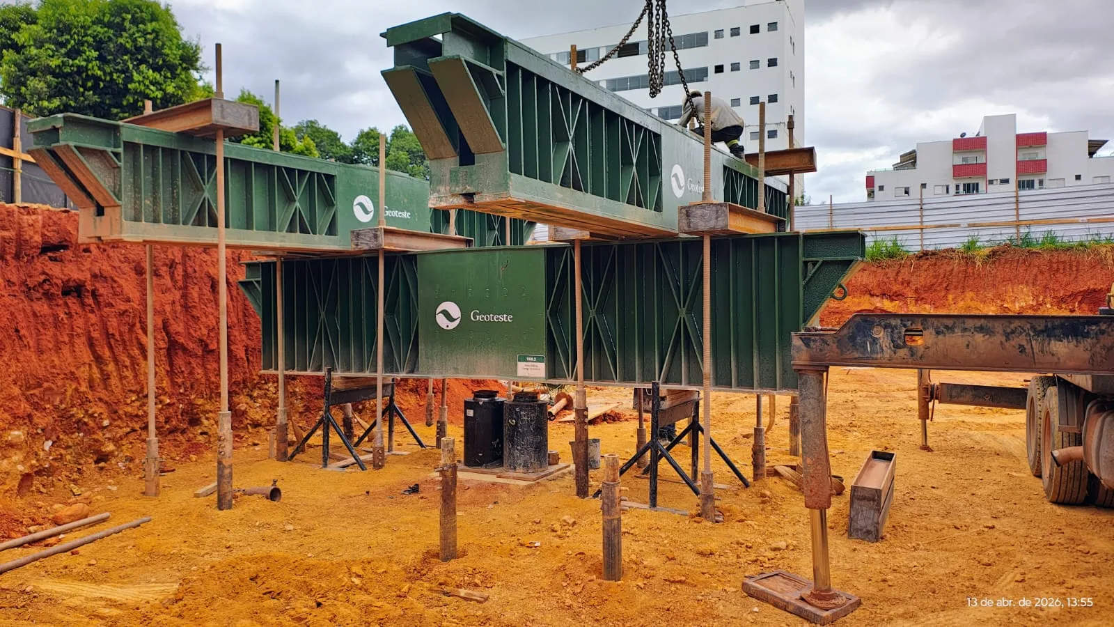
Setting up a static pile load test requires engineering planning, as it involves mobilizing large forces in a construction site environment. The setup comprises three fundamental subsystems: the reaction system, the load application and measurement system, and the reference system for displacement measurement.
Reaction systems: tie-downs, reaction piles, and kentledge
To apply a compressive force at the top of the test pile, it is necessary to have a system capable of resisting the upward reaction with full stability. There are three main configurations:
- Tie-downs anchored in the ground: high-strength steel bars anchored in rock mass or competent soil layers using cement grout. It is a clean solution with high capacity for elevated loads.
- Reaction piles: deep foundation elements subjected to tensile loads by lateral friction along the shaft. The geometric arrangement and spacing relative to the test pile must comply with the minimum distances specified in ABNT NBR 16903:2020 to prevent mutual interference and overlap of stress bulbs, with recommended center-to-center spacings of at least three to five diameters, respecting a minimum physical limit of two and a half meters.
- Kentledge: a platform loaded with concrete blocks, metal ingots, or crushed stone boxes. This mass generates a direct gravitational reaction on structural steel beams, requiring strict attention to the stability of the supporting ground to prevent overturning or excessive surface settlements.
Load application and measurement system
The vertical force is generated by one or more hydraulic jacks operated by a manual or electric pump. The jack rests on the load distribution plate at the top of the tested pile and reacts against the main steel beam of the reaction system.
The magnitude of the applied force must be monitored by instruments calibrated according to the standards of the Brazilian Calibration Network (RBC). NBR 16903:2020 requires the use of properly calibrated electronic load cells or precision pressure gauges associated with hydraulic jacks with a recent calibration curve. The use of a load cell inserted directly into the force line offers greater precision by eliminating distortions caused by internal friction of the hydraulic pistons.
Instrumentation for displacement measurement
The axial displacements experienced by the top of the pile are measured by mechanical dial gauges or linear electronic transducers (LVDT), with a minimum resolution of 0.01 millimeter. The standard specifies the diametrically opposed positioning of at least four instruments arranged at 90 degrees to each other, allowing the identification of any loading eccentricities or rotations at the top of the element.
These sensors are fixed on independent reference beams, commonly called deflection reference beams. The supports of these beams must be positioned at normative safe distances from both the test pile and the reaction elements, preventing surface soil movements during loading from falsifying sensor readings.
Operational procedures and loading modalities
The test is conducted in successive load stages, where each increment represents a percentage fraction of the pile's predicted working load, typically in fractions of 10% to 20%. The test modalities differ mainly in the criterion for the duration of each loading stage.
Slow loading test
In slow loading, each load stage is maintained until complete settlement stabilization. According to NBR 16903:2020, settlement is considered stabilized when the deformation rate is below the normative limit set within the specified time interval, typically less than 5% of the total settlement observed in that stage over a one-hour period. This modality representatively reproduces the static behavior under long-term loading, being the primary reference in geotechnical engineering.
Rapid loading test
In rapid loading, load stages are maintained for predetermined and constant time intervals, regardless of the absolute stabilization of deformations. It is frequently employed in systematic quality control campaigns for works where the executive schedule does not accommodate the temporal extent of slow loading, requiring, however, careful calibration and correlation with the long-term behavior of the soil.
Loading and unloading cycles
After reaching the planned maximum load or a prescribed displacement level, the test follows a progressive unloading sequence. Loading and unloading cycles allow separating the total recorded deformation into two essential mechanical portions: elastic settlement (restitution) and plastic residual settlement. The proportion between these portions reflects the degree of soil plastification and the structural stress state of the pile.
| Loading Modality | Criterion for Stage Change | Typical Duration per Stage | Preferred Application |
|---|---|---|---|
| Slow Loading | Settlement stabilization according to normative limits | 1 to 2 hours (or more, depending on the soil) | High-relevance projects, critical works, and design validation |
| Rapid Loading | Fixed and predetermined time per stage | 5 to 15 minutes per increment | Quality control and comparative validation on construction sites |
| Cyclic Loading | According to programmed cycle schedule with reloading | Variable according to specific objective | Evaluation of cyclic degradation, residual friction, and system fatigue |
Data interpretation: from the load-settlement curve to bearing capacity
Raw data collected in the field provide three primary interdependent variables: applied force, displacement, and time. The processing of this data results in the construction of the load-settlement curve, an elementary graphical representation for analyzing the foundation's behavior.
Construction and analysis of the load-settlement curve
The plot of the load-settlement curve shows the initial stiffness of the assembly, the beginning of yielding of the lateral friction resistance along the shaft, and the subsequent mobilization of toe resistance. In friction piles, the curve tends to show a distinct inflection early in the displacements. For piles that significantly rely on end-bearing resistance, significantly larger settlements are required for total resistance to be fully mobilized.
Extrapolation methods and conventional failure criteria
In most compression load tests, the maximum load reached by the equipment does not achieve the physical geotechnical failure of the element, characterized by continuous settlements without an increase in load. When physical failure does not occur, engineering resorts to mathematical extrapolation formulations or performance limit conventions:
- Van der Veen's method: adjusts an exponential curve to the experimental points, allowing the estimation of the ultimate failure load through mathematical curvature parameters.
- Davisson's criterion: a widely used method that establishes a displaced elastic line, associated with the elastic shortening of the pile combined with a fixed plastic displacement corresponding to the element's thickness and diameter.
- ABNT NBR 6122:2022 criteria: determine the conventional failure load through plastic displacement limits or the application of coefficients on the stiffness measured on the experimental curve, setting objective criteria for defining the design geotechnical resistance.
Preparation of the technical report
The final step of a load test is the issuance of the conclusive technical report. This document must include all registration data of the tested pile, such as cutoff elevation, local stratigraphic profile, date and method of execution, calibration reports of equipment and transducers, complete tables of readings at each stage, load versus displacement and time graphs, in addition to the calculation memory of the interpretive methods applied.
Execution of load tests with Geoteste
Geoteste excels in the planning, setup, and execution of static pile load tests, rigorously adhering to the parameters of ABNT NBR 16903:2020 and supporting designers and contractors in the analyses required by ABNT NBR 6122:2022. With structured reaction systems, certified load cells, and high-precision electronic instrumentation, we provide reliable readings that eliminate geotechnical uncertainties in the field.
Our technical team supports your project from the conception of the reaction system and choice of loading modality to the computational processing of load-settlement curves and determination of the actual bearing capacity of foundation elements. Contact our specialists and request a technical evaluation for your project.