Loading challenges in large capacity piles
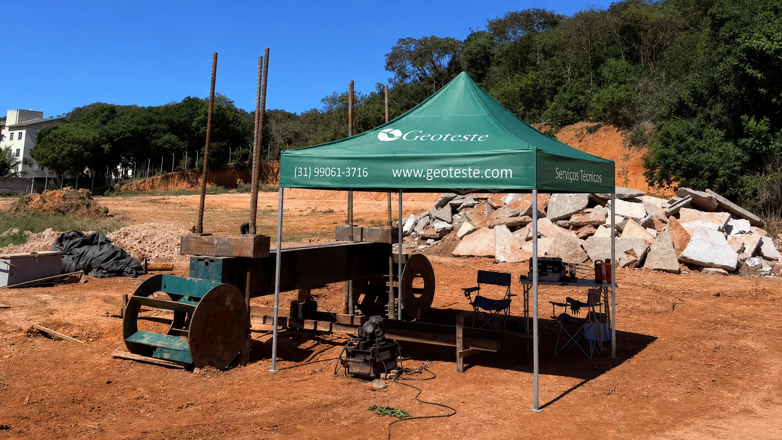
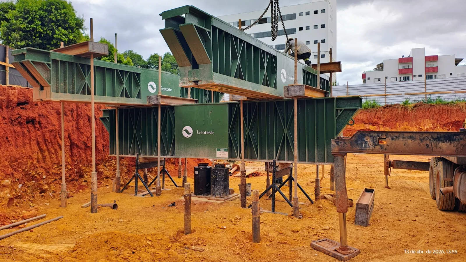
The design of deep foundations for infrastructure works, large buildings, and bridges frequently results in bored piles, barrettes, or caissons with load capacities exceeding thousands of kilonewtons. Verification of the performance of these foundations through conventional static tests imposes severe logistical and financial obstacles. The traditional static load test applied at the top requires reaction systems of monumental proportions, either by kentledge composed of concrete blocks and gravel boxes, or by sets of tie-downs and reaction piles anchored in the ground.
In foundation elements with high working loads, assembling a top kentledge can involve critical operational risks, unfeasible construction site areas, and costs that rival the cost of the foundation itself. To resolve this geotechnical impasse and enable technological control according to the guidelines of ABNT NBR 6122:2022, the use of the bi-directional test, also known by the acronym PCB or Osterberg cell test (O-cell), has become consolidated in national and international engineering.
Operating principle of the expansive cell
The bi-directional load test is based on the installation of one or more expansive hydraulic cells inside the pile shaft, at a predetermined elevation before concreting. This cell, manufactured from high-strength steel, acts as a disposable hydraulic jack integrated into the reinforcement of the structural element itself.
Unlike the conventional top-down test, where force is applied downwards against an external reaction, the bi-directional cell applies equal and opposite axial forces within the element:
- The upper segment of the pile is pushed upwards, mobilizing the skin friction along the section above the cell, counterbalanced by the self-weight of the concrete in that segment.
- The lower segment of the pile is pushed downwards, mobilizing the end-bearing resistance of the pile combined with the skin friction of the section below the cell.
The structural element itself provides its mutual reaction. The upper part serves as a reaction for the loading of the lower part and vice-versa. This mechanical principle eliminates the dependence on heavy steel beams, anchor ties driven around, or kentledge on the surface, allowing the mobilization of static loads of the order of tens of meganewtons safely on the construction site.
Definition of installation elevation and equilibrium point
The success of the bi-directional load test lies in the rigorous determination of the level at which the expansive cell should be positioned. As discussed in national geotechnical literature, including Thais Lucouvicz Dada's master's dissertation presented at the University of São Paulo in 2019 and publications in the annals of the Seminar on Special Foundations and Geotechnical Engineering (SEFE), the ideal elevation corresponds to the equilibrium point of mobilizable resistances.
In geotechnical terms, the aim is to position the device so that the maximum load capacity of the upper segment is similar to the maximum capacity of the lower segment:
- Estimated upward capacity: corresponds to the skin friction of the upper section minus the self-weight of the pile above the cell.
- Estimated downward capacity: corresponds to the end-bearing resistance plus the skin friction of the lower section and the self-weight of the lower segment.
If the cell is installed in a very shallow position, the upper lateral resistance may be exhausted prematurely, with the upward segment reaching excessive displacements before the end-bearing resistance of the lower section is properly mobilized. If installed excessively close to the tip without considering the type of basal soil, the tip may settle without the upper skin friction being tested to significant levels. In long piles that cross heterogeneous soils or are embedded in rock, it is possible to design multi-level arrangements, with cells installed at different elevations to isolate and evaluate different stratigraphic horizons.
System components and field instrumentation
The bi-directional system operates as a rigorously monitored deformation and loading test. The instrumental assembly is composed of robust elements capable of withstanding the concreting environment and working pressure:
- Expansive cell: formed by parallel metal plates and sealed hydraulic diaphragms, designed to open under oil injection at controlled pressures.
- High-pressure hydraulic lines: steel pipes connected to the cell that run up, fixed to the reinforcement, to the top of the pile, connecting to the hydraulic pump.
- Internal reference rods (telltales): protective tubes installed inside the reinforcement that house metal rods anchored immediately above and below the cell. These rods transmit to the top the exact mechanical measurement of the device's opening, decoupling the displacement of structural expansion from the elastic deformations of the shaft.
- Electronic displacement transducers (LVDT) or dial gauges: positioned on top reference beams to record the absolute elevation of the pile top and the movement of the internal rods.
- Electrical extensometers or vibrating wires: arranged along the shaft at strategic levels to determine the distribution of skin friction along the depth.
Execution procedure and applicable standards
The execution of the bi-directional load test involves integrated planning between drilling, reinforcement, and concreting. The reinforcement cage receives the cell assembled with alignment guides and passage tubes to ensure the continuity of concrete flow. The concrete must be placed through a tremie pipe that passes through the cell plane, ensuring that the lower and upper elements avoid segregation zones or air pockets.
Regarding normative aspects, the performance of static load tests on deep foundations in Brazil is guided by ABNT NBR 16903:2020 and required under specific conditions by ABNT NBR 6122:2022. However, as NBR 16903 predominantly focuses on tests with load application at the top, the indispensable international technical reference for bi-directional tests is ASTM D8169/D8169M-26 (Standard Test Procedures for Measuring the Axial Compressive Response of Deep Foundations Elements Under Bi-Directional Static Axial Compressive Load).
The procedure follows slow or rapid loading stages, recording the following parameters at each interval:
- Hydraulic pressure and corresponding force generated by the cell.
- Upward displacement of the top of the cell.
- Downward displacement of the base of the cell.
- Displacement of the pile head at the surface.
- Specific strains measured by extensometers along the shaft.
Interpretation and construction of the equivalent load-settlement curve
During the test, the raw data generates two independent load versus displacement curves: the upward movement curve of the upper shaft and the downward movement curve of the tip and lower shaft. From this data, geotechnical engineers perform the conversion to the traditional top load-settlement curve (fictitious conventional top test).
The most widely applied analytical method in engineering was proposed by John Schmertmann in 1989 and further developed by various authors, consisting of summing the components for each level of common settlement:
- For a given displacement value, the force mobilized by the lower segment and the force mobilized by the upper segment are determined.
- The additional elastic shortening that the upper segment would undergo if the entire load were applied at the top is calculated, considering the compressibility of the concrete and the load transfer rate due to friction.
- The load of the upper section is summed with the load of the lower section, adjusting the settlements by the calculated elastic shortening, obtaining the equivalent behavior of conventional top loading.
This interpretation allows assessing not only the total resistance mobilized, but also individualizing the portion of skin friction and the portion of end-bearing resistance with superior technical reliability compared to uninstrumented conventional load tests.
Comparison between static load test methods
The choice between the bi-directional method and the top-down loading method involves geometric aspects, load magnitudes, and physical limitations of the work:
| Criterion | Conventional Top Load Test | Bi-directional Load Test (PCB) |
|---|---|---|
| Reaction system | Requires external kentledge or reaction piles and tie-downs | Self-reacting through the friction and tip of the pile itself |
| Required physical space | Large free site area for beams and supports | Confined exclusively to the diameter of the pile under test |
| Maximum test capacity | Limited by the feasibility of beams and tie-downs (generally up to 30 MN) | Capable of reaching forces exceeding 100 MN with multiple cells |
| Separation of tip and friction | Requires detailed instrumentation along the entire shaft | Intrinsic separation between upper and lower sections |
| Pile use after test | Pile preserved directly for structure support | Requires cement grout injection into the cell for shaft recomposition |
Structural recomposition of the pile with grouting
As the expansive cell opens during the test and creates a mechanical void in the concrete, the tested pile would suffer a structural discontinuity if this space remained open. When the tested pile is a sacrifice element, executed only for project calibration before the start of the main foundations, this condition does not interfere with the work.
However, when the test is performed on a production pile that will integrate the definitive superstructure, the system must be designed with post-test grouting ducts. Once the unloading stage is completed, cement grout or high-strength micro-expansive grout is injected into the cell and the annular space opened between the metal plates. The controlled injection restores the structural integrity of the shaft, re-establishing the integral transmission of permanent structure axial loads to the pile base.
Geoteste technical support in high-capacity tests
Geoteste specializes in deep foundation control and verification engineering, offering comprehensive technical support for the planning, instrumentation, execution, and interpretation of bi-directional load tests. The company's technical staff operates in accordance with ABNT NBR 6122:2022, ABNT NBR 16903:2020, and the international ASTM D8169/D8169M-26 standards, ensuring rigor in defining the cell setting elevation, precision in displacement monitoring, and analytical reliability in generating the equivalent load-displacement curve.
To enable static tests on large-diameter piles without the restrictions and costs of external reaction systems, count on the experience of Geoteste's engineering team. Contact our specialists to size the appropriate test arrangement for the geotechnical specificities of your project.